Cub Cadet RZT-S Series User Manual
Page 56
RZT-S
50
13.
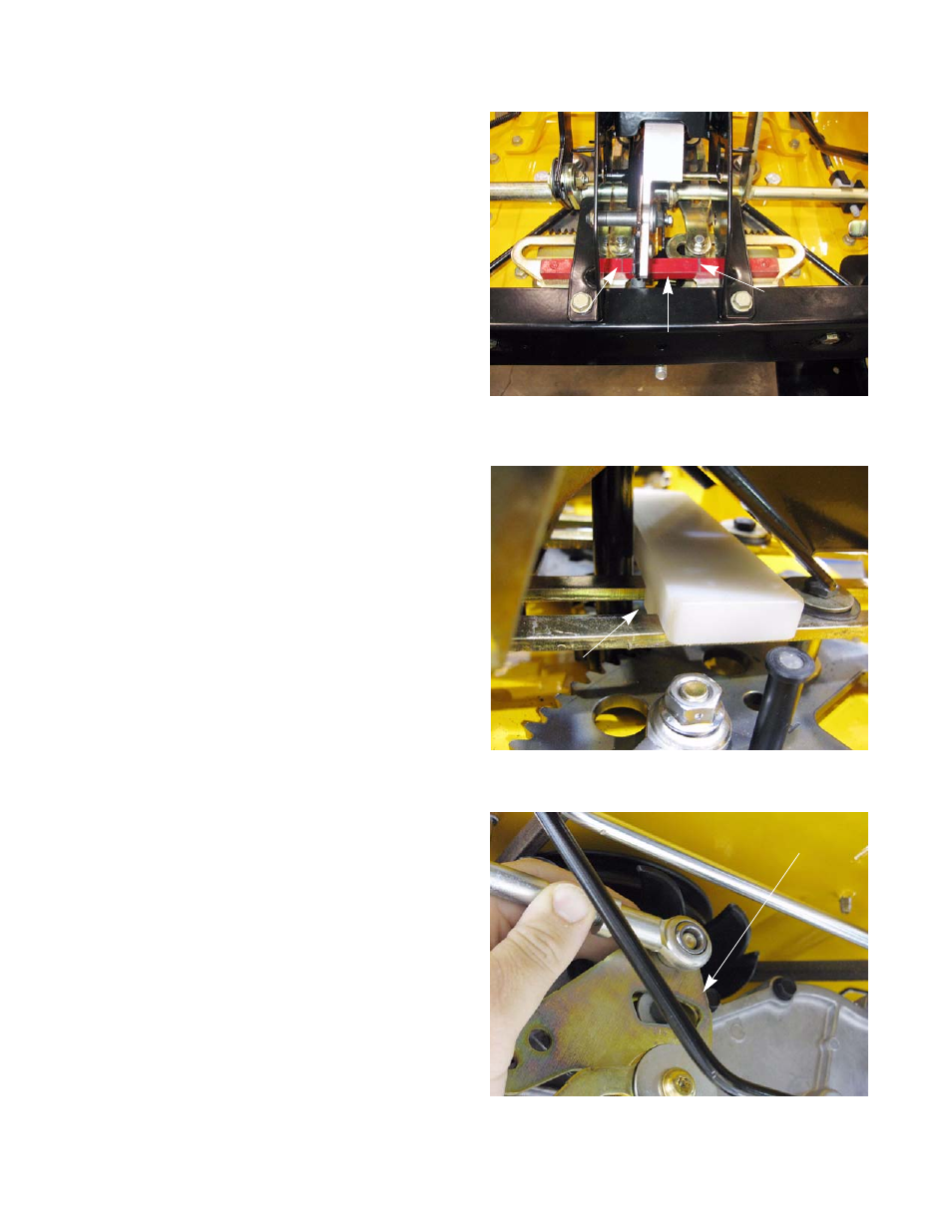
Install the speed cam alignment bar.
See Figure 5.6.
14.
Install the control link alignment fixture in the slots of
the control links. See Figure 5.7.
NOTE: Make sure the bolts in the cam slots are
aligned with the speed cam timing marks.
15.
Thread the ball joints up or down the length of the
control links to align them with the holes in the
transmission control arms. See Figure 5.8.
16.
Attach the control links to the transmission control
arms.
17.
Tighten the control link jam nuts.
18.
Remove all of the alignment pins and alignment fix-
tures.
19.
Install the floor pan, following the procedures
described in Chapter 3: Body.
20.
Test drive the mower in a safe area before returning
it to service.
NOTE: Do not put a mower back into service if it
does not react properly to control inputs.
Figure 5.6
Speed cam alignment bar
Timing mark
Timing mark
Figure 5.7
Control link alignment fixture
Figure 5.8
Control arm
- G1332 (20 pages)
- i1046 (36 pages)
- i1046 (32 pages)
- 54M (28 pages)
- 980 (20 pages)
- 949 (20 pages)
- Time Save (28 pages)
- 990 (24 pages)
- 997 (36 pages)
- V469 (20 pages)
- 4 Fabricated Deck (36 pages)
- 4 Fabricated Deck (32 pages)
- 6 Fabricated Deck (28 pages)
- 4 Fabricated Deck (32 pages)
- 4 Fabricated Deck (32 pages)
- 6 Fabricated Deck (36 pages)
- M48-M60-KW (28 pages)
- 4 Fabricated Deck (32 pages)
- 6 Fabricated Deck (32 pages)
- CC 500 BAT (30 pages)
- CC 22 (20 pages)
- CC 949 (13 pages)
- 33" Wide Area (29 pages)
- Z-Wing (88 pages)
- TANK S Series: Electrical System (9 pages)
- TANK S Series: Hydraulic Drive & Steering System (12 pages)
- TANK S Series: Steering System Adjustments (11 pages)
- 640 (24 pages)
- 640 (20 pages)
- 641 (24 pages)
- 641 (20 pages)
- J466 (32 pages)
- Series C460 (28 pages)
- 435A (24 pages)
- 642 (24 pages)
- 414 (24 pages)
- M465 (28 pages)
- Fun Runner (117 pages)
- 4 x 2 Big Country - Steel Bed (38 pages)
- 4 x 2 Big Country - Poly Bed & Steel Bed (82 pages)
- 4 x 4 Volunteer (328 pages)
- 6 x 4 Big Country (121 pages)
- CC 4BP 32cc (29 pages)
- 2518-48 (60 pages)
- 1525 (39 pages)