Checkline DTMX User Manual
Page 5
4.00 QUICK START INSTRUCTIONS
4.10 Setup
1. Insert a sample of the process material into the Thickness Compensator and
secure the ends of the sample under the Sample Holding Clips on each side
of the unit. Thickness Compensator is not used on the DTMX-200
Model.
2. Set the Material Rigidity Selector to "TEX” or "WIRE"
3. Set the Field Calibration Adjustment to "STD”
4.20 Operation
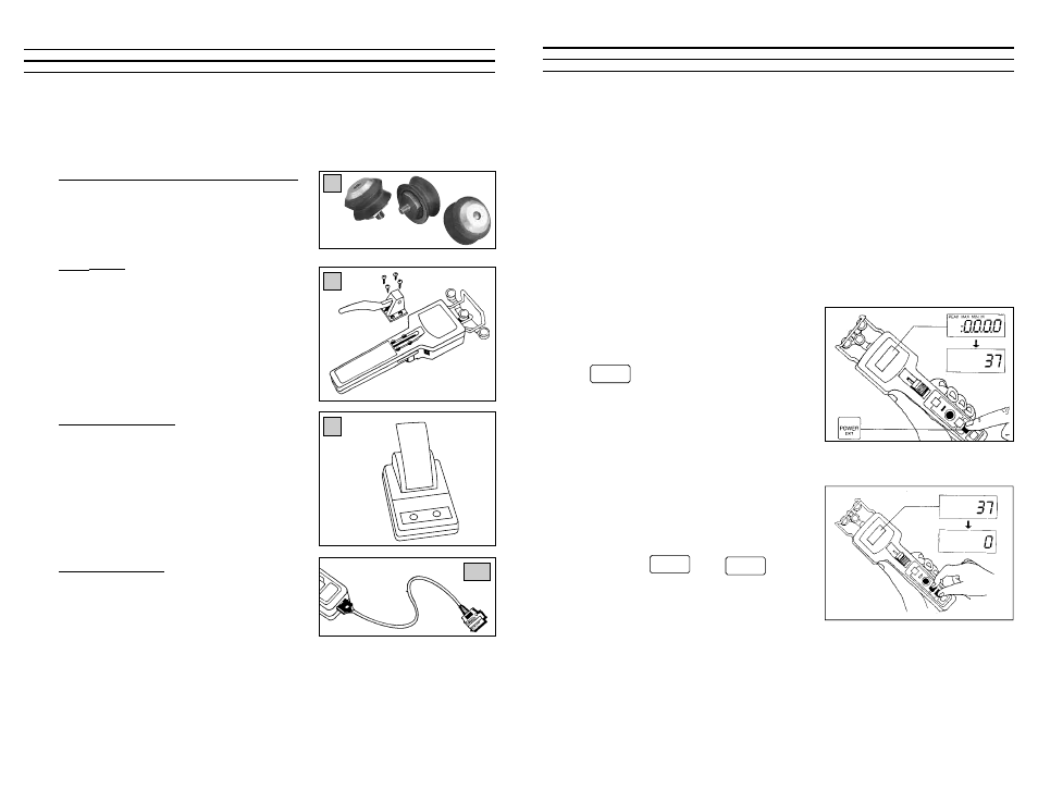
1. Turn the unit on by pressing the
key. Display should show zero
when unit is in measuring position. If
the gauge displays zero go to Step 3,
otherwise perform a Gravity Correction
Procedure (Step 2).
2. Position the DTMX into the measuring
position and perform a Gravity
Correction procedure (Zero):
Press the and keys
simultaneously, and hold until the display
shows “0” or “0.0”.
POWER
EXIT
POWER
EXIT
RECALL
5
9.50 Options
9.51 Ultra-High Speed Roller Assemblies
For line speeds up to 5,000 m/min, specify
“U” roller guides.
9.52 Lever
For high tension ranges specify an “L” Lever
attachment to make it easier to push the
outer rollers forward for material acquisition.
9.53 Portable Pinter
The P-DTMX battery-powered, portable print-
er uses rechargeable batteries. It is supplied
with a 10 ft. connection cable, one roll of
paper and a 115 VAC charger.
9.54 Serial Cable
The CS cable is for connection to Personal
Computers. The 10 ft. cable is supplied with
DB9 and DB25 Serial connectors.
28
U
L
P
CS