Checkline DTMX User Manual
Page 13
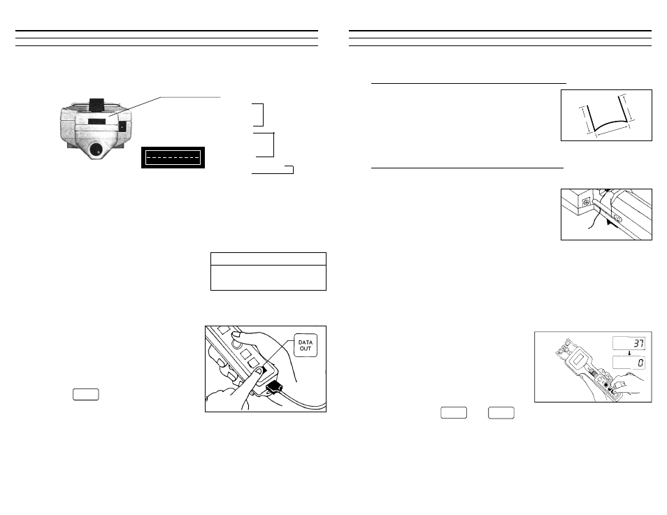
5.51 Preparing Sample For Thickness Compensator
When using monofilament, wire or other difficult-
to-bend materials, the sample must be prepared
properly before inserting into the Thickness
Compensator. Using the pliers supplied, bend the
sample as noted in the sketch. For monofilaments,
maintain arc “A” as shown, so sample bends into anvils.
5.52 Inserting Sample Into Thickness Compensator
Push the Thumbpiece forward to separate the two anvils. Insert the sample
into the slot and slowly release the Thumbpiece
back to its resting position. The material sample
should be secured between the two anvils. Place
the ends of the sample under the Sample Holding
Clips located on each side of the unit.If the ends
stick up bend them back so they will not present a
safety hazard.
NOTE: In lieu of a sample, an equivalent shim can be inserted into the
Thickness Compensator as long as its compressed thickness is the same as the
process material. The shim should be secured using a spray adhesive on one
side, so it will not fall out each time the Thumbpiece is pushed forward.
5.60 Gravity Correction Procedure (ZERO)
The DTMX is factory calibrated for use in
the right-handed, horizontal position (verti-
cal material path) with the rollers aligned
vertically. When using the DTMX in any
other orientation, a Gravity Correction
Procedure (Zero) should be performed.
Hold the instrument in the measuring posi-
tion and press the and keys simultaneously. The display
will show zero. The DTMX is now ready for use.
13
1-1/4"
1-1/4"
1-1/2"
POWER
EXIT
RECALL
Sample Holding Clip
arc A
7.20 Output Connector Pin Outs
7.30 Analog Output
The analog output permits users to connect the DTMX to Chart Recorders and
other analog recording devices for trending and other data recording purposes.
The analog output is continuously updated at all times and does not have to be
turned on or off.
Signal Type
0-1 VDC
D-to-A Converter
12 bit
Frequency Response 16 msec (62.5 Hz)
Impedance
2 K Ohm (minimum)
7.40 Serial Output — Printer
The DTMX can be connected to the
CHECK•LINE P-DTMX battery-powered
printer (or other serial printer) for download-
ing the recorded data and all calculated statis-
tics.
Press the key to print recorded data.
Note: When the CHECK•LINE P-DTMX is
ordered, no printer setup is required.
20
Pin #
Function
9 . . .
Signal (0–1) VDC
10 . . .
Ground
xxxxxxxxx
10-Pin Output Connector
1 RXD
2 TXD
3 CTS
4 RTS
5 REQ
6 READY
7 CLK
8 DATA
9 Signal 0–1VDC
10 GND
DATA
OUT
RS-232C
Digimatic
Analog
10
1