Checkline DTMX User Manual
Page 10
10
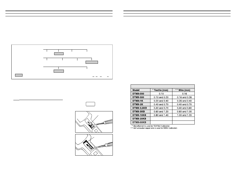
5.30 Configuring Dip Switches
The DTMX is supplied with six (6) dip switches permitting the user to select
desired Display Update Rate, Memory Mode and Data Output Type as detailed
below.
To access the dip switches, the Thumbpiece and Slide Guide Plate must be
removed. Refer to access instructions below.
5.31 Accessing The Dip Switch Block
1. Turn the DTMX power off by pressing and holding the
key
for five (5) or more seconds. The display will go blank.
2. Using a small Phillips screwdriver, remove
the screw in the center of the Thumbpiece.
Remove the Thumbpiece and screw. The
Slide Guide Plate and screw will be visible.
3. Using a small Phillips screwdriver, remove
the screw at the bottom of the Slide Guide
Plate and remove plate.
Display Update Rate
Memory Mode
Data Output Type
0.5 sec.
1 sec.
2 sec.
4 sec.
RS-232C
Digimatic
Standard
Standard-NAPO
On Demand
Continuous
= Denotes Factory Setting Standard N A P O = Standard Memory with No Auto Power Off
POWER
EXIT
Slide Guide
Plate
Thumbpiece
8.00 CALIBRATION
The DTMX is factory calibrated by taking a series of measurements with
known weight standards suspended from Factory Calibration Standard
Materials. The built-in microprocessor uses this calibration data with a com-
plex formula to calculate a calibration curve which takes into account material
rigidity, material thickness and orientation of use. The factory calibration
works well in most cases. However, if the process material to be measured dif-
fers significantly from the Factory Calibration Standard Materials (see table
below) or if the application requires the highest accuracy possible, perform a
Field Calibration Adjustment (refer to Section 8.20) or return the gauge to the
factory for optional Special Calibration.
Note: When ordering a Special Calibration, please supply a 10' sample of the
process material for calibration purposes.
Factory Calibration Standard Materials
Customer Sample
Customer Sample
Customer Sample
Customer Sample
23