Checkline ETW User Manual
Page 8
Electromatic Equipment Co., Inc.
-8-
3.7
Set Mode - Torque & Angle
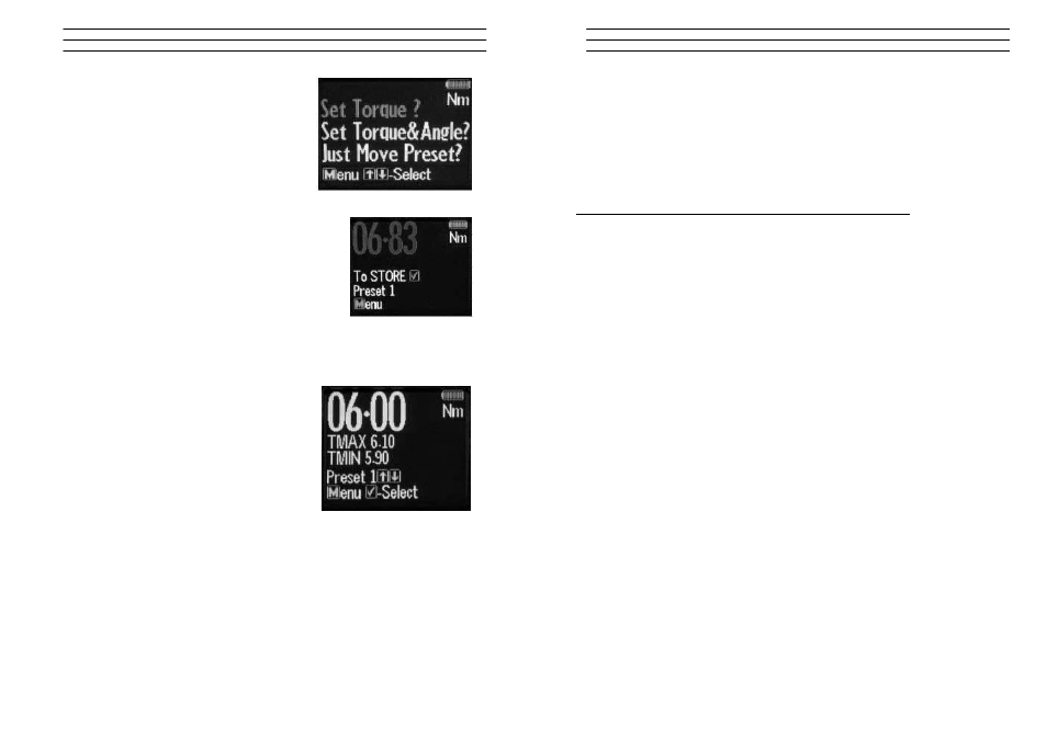
1. Press MENU to Scroll to Set Mode, Press
OK and you'll see option to "Set Torque" or
"Set Torque and Angle" or "Just Move Preset"
2. If you are setting a Torque only preset see
page 8 of these instructions.
3. Press UP or DOWN To select select "set
Torque and Angle" and press OK when high-
lighted green
4. Press To select the Preset number you want
to use and press OK
5. Press UP or DOWN to select your preset
Torque and press OK
6. Press UP or DOWN To set the Angle preset
Value and press OK
7. Press MENU to go to Preset menu
8. Press UP or DOWN to select the Preset
location
9. Press OK to select your required Preset and
take measurements
10. Press OK to store the readings you are taking
3.8
Set Mode – Torque
1. Press MENU to Scroll to Set Mode
2. Press OK to select and UP or DOWN to
select type of Preset, Set Torque or Torque
and Angle
3. Press OK to select Torque
4. Press UP or DOWN to select Set by % or Set
by Tolerance
5. Press UP or DOWN to Scroll to required
Preset No. (1 to 99)
6. Press OK to Confirm Preset No. selected
7. Press UP or DOWN to Set Nominal Value and press OK
8. Press UP or DOWN to Set Your Low Value and press OK
9. Press UP or DOWN to set your High Value and press OK
10. Use MENU to select Preset from the menu to use this set-up
To set a Preset as a +/- % Deviation of the Nominal Value, Please select "Set
Torque" and then select "by %"
Electromatic Equipment Co., Inc.
-13-
4.2
Torque and Angle Calibration
1. Immediately after the regular Calibration the user is prompted to "wait" - the
Gyroscope is doing a self test at this stage
2. The user is then prompted to rotate the wrench by 180 degrees and press OK to
complete the calibration
4.3
Communication to PCFE
To Establish Communication with the Wrench - Using RS232 Cable
1. Place the RS232 Cable in the COM 1 PC Port. Note: Available PC Port
configurations may vary. It is important that communications are attempted with
the correct PC Port. The PC Link has been designed for connection with the
standard 9-Way D-Type PC Port.
2. Place the other end of the cable into the wrench Jack Plug socket.
3. Switch on the wrench by pressing any button on the wrench. Select the correct
Com port on the PCFE. Now the PCFE will automatically connect to the wrench
and the screen will fill with data from the wrench
4. When you are finished communicating with the wrench, remove the cable from
the wrench.
4.4
Communication using USB Cable
1. The installation checks the PC for the .net framework and installs it from the web
if required.
2. Install the USB driver - It can be found at C:/program files/PCFE/Front-end/USB
drivers. After PCFE installation, the PC wizard will ask you to install this driver
for the new hardware
3. The PCFE Icon is on the desktop, the password is "master" - you can re-size the
screen and it will remember this setting on next time of opening.
The PCFE communication operates as follows:
Firstly connect USB cable to PC and to the Wrench or screwdriver and power up the
tool. Open the PCFE with "master" as the password, This password can be changed
see page 16 Select Com port.
there will be two options :
1. Com Port 1 - this will allow you to connect the older type tools using the RS232
cable.
2. Com port x - it 's a virtual port and will vary from PC to PC.
Note : After you configure or view data on the Wrench and disconnect from PCFE,
select Com port 1 afterwards to close the virtual port.