Operating, maintaining and servicing the cav, Cav components – Cannon Instrument CAV-2000 User Manual
Page 75
69
CANNON
®
Automatic Viscometer Models CAV-2100 and CAV-2200 with VISCPRO
®
Instruction & Operation Manual
Version 2g — May, 2009; CANNON
®
Instrument Company
2139 High Tech Road • State College, PA 16803 • USA
CHAPTER
5
OPERATING, MAINTAINING
AND SERVICING THE CAV
This chapter of the CAV Instruction & Operation Manual contains
information regarding the operation, service and maintenance of the CAV
instrument. For additional information on required utilities, instrument
installation and setup, refer to the Installation & Setup Guide.
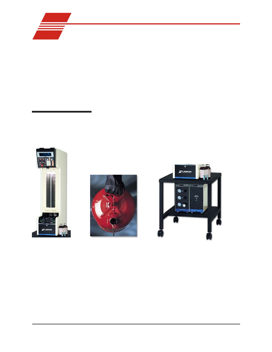
CAV components
The standard CAV installation includes these primary components:
Bath unit
User-supplied solvent & waste vessels
Service/Dispensing Units
Bath Unit
The Bath Unit houses the primary control and operating systems for the
CAV. The lower section of the Bath Unit includes a pneumatics drawer
with electronic components and pneumatic controls. The middle section
of the Bath Unit includes the sample table, sample trays, and the tempera-
ture bath with viscometer tubes. The upper chassis is located above the
bath and includes the control panel and additional control hardware and
electronics for Local and Remote mode operation including sample
testing, viscometer tube cleaning, and calibration.