7 .8 changing the suction and pressure tubing – BUCHI Pump Module C-605 User Manual
Page 39
7 Maintenance
39
Pump Combinations Operation Manual, Version E
1
2
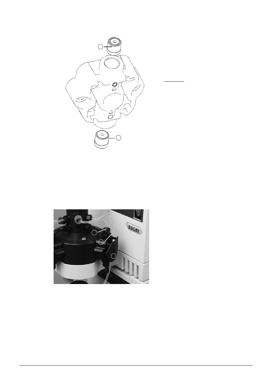
Fig. 7.5: Installing the new valves
• Remove the valve screw fittings and tubing.
• Remove the valves and insert the new valves.
The inlet valve is marked by one ring a at the
head end, and is attached with that ring facing
the pump head in the direction of the arrow.
The outlet valve is marked by two rings b at
the head end and is inserted into the pump with
the unmarked side first. The valves are posi-
tioned loosely in the pump head.
To prevent them from falling out:
• Take the pump head between thumb and index
finger and keep the valve opening shut.
• Hold the pump in a horizontal position.
• Screw the suction tubing onto the inlet valve.
• Screw the pressure tubing onto the outlet valve
and attach the pump head vertically onto the
piston of the pump housing with the arrows
facing upward.
• Screw on the pump head tightly.
• Mount the suction tubing and the pressure
tubing to the distributor with the turix wrench.
• Press the suction tubing into the depression of
the pump head.
• Attach the pump head cover to the pump head.
7 .8
Changing the suction and pressure tubing
1
3
2
Fig. 7.6: Installing the connection tubing at the pump
head
To change the suction and pressure tubing, proceed
as follows:
• Using the turix wrench, loosen both valve screw
fittings of the suction and pressure tubing and
pull them out.
• Remove the ferrule, cone ring and valve screw
fittings on all tubing. The ferrule must be
replaced; the cone ring and valve screw fittings
may be reused if they are not damaged.
• Attach the valve screw fitting, with the square
side first, to the ends of the suction and pres-
sure tubings.
• Mount the cone ring and ferrule according to
figure 5.5.
• Proceed as above for the ends of all tubings
that you wish to replace.
• Screw the tubings back into their mountings.
• Tighten the valve screw fitting a using the turix
wrench.
• Press the suction tubing into the depression of
the pump head b, and attach the pump head
cover c to the top.