BUCHI Pump Module C-605 User Manual
Page 23
5 Putting into operation
23
Pump Combinations Operation Manual, Version E
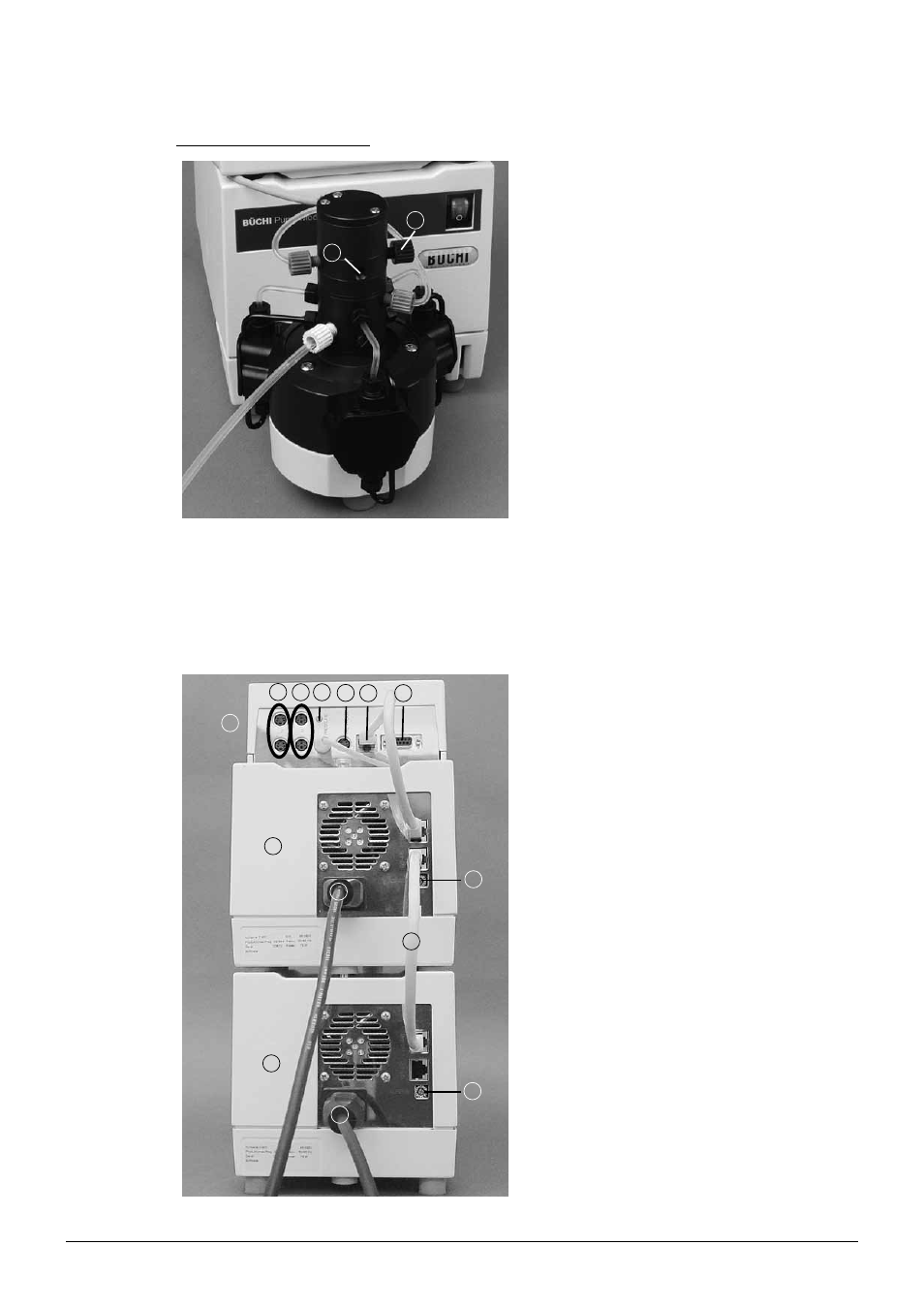
Pressure tubing 1/8” x 1/16”:
1
2
Cut the pressure tubing to the desired length. Attach
the fitting and the ferrules to one end of the tubing
as described.
Screw the fitting into the upper output of the
separator head a. Make sure that all fittings are
hand-tight.
Inlet b is only needed if two pump modules are
used. If only one pump module is used it has to be
shut with a blind plug.
Fig. 5.13: Pump head with connected pressure tubing
5 .3 .4
Pump system 3: Pump Manager C-615 and 2 Pump Modules C-601 or C-605
NOTE
You can connect two pump modules to the pump manager if both modules are of the same type.
5
7
1
3 4
8
6
2
11
11
7
9
10
12
One pump module has the address selector switch
set to A (factory setting), the other has the selector
switch set to B.
Place the first pump module l on a level surface.
Make sure the address selector switch is set to B
j. If not, take the screwdriver and turn the small
white dot to B. Make sure the selector switch of
the second pump module l is set to A i. Place
the pump module on top, and press firmly from the
back, or place it next to the other. Connect both
pump modules to the power supply k.
A holding angle is located in the center back of the
pump manager b. Remove it.
There is a rail located at the bottom of the pump
manager. Slide it from the front to the end of the
stop on the pump module. Attach the holding
angle.
Connect the two pump modules l a to the pump
manager b by means of the cable RJ45 g.
c
LEVEL: Port for optional solvent level sensor
d VALVE: Port for optional solvent valve
e PRESSURE:
Port for level sensor
f TTL IN/OUT: TTL connection
h RS 232: Serial output signal
Fig. 5.14: Electrical installation