BUCHI Pump Module C-605 User Manual
Page 21
5 Putting into operation
21
Pump Combinations Operation Manual, Version E
5 .3 .3
Pump system 2: Pump Manager C-615 and 1 Pump Module C-601 or C-605
The “or” between 601 and 605 indicates that operation is either possible with Pump Module C-601 up
to 10 bar or with Pump Module C-605 up to 50 bar.
1
2
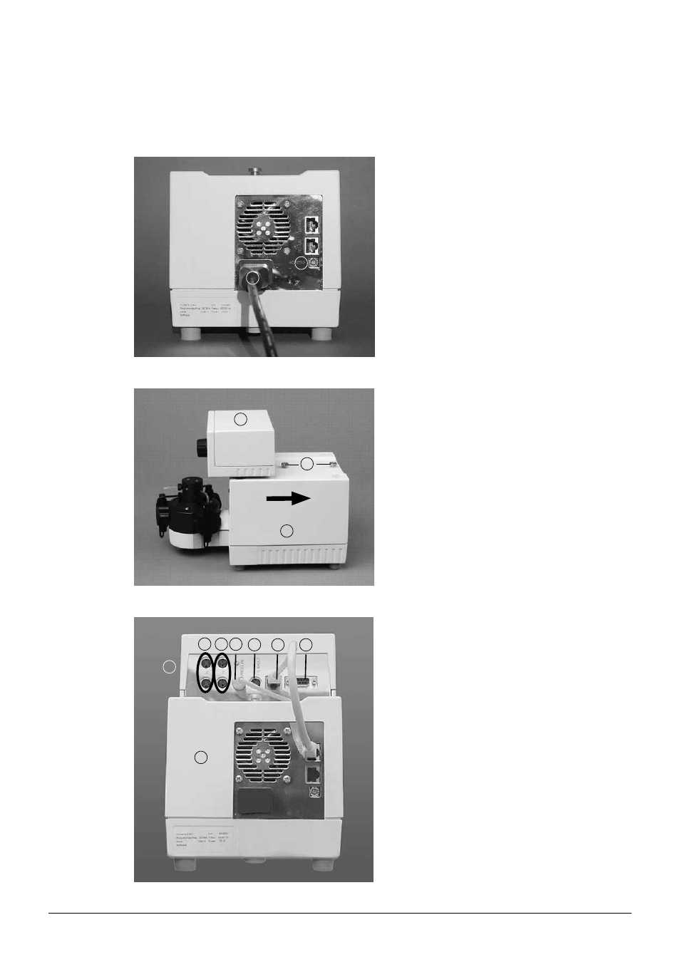
Place the pump module on a level surface. Connect
the power cord. Make sure that the address selector
switch is set to A a. If not, take the screwdriver and
turn the small white dot to A. Connect the power
cord b.
Fig. 5.8: Rear connections of the pump module
1
2
3
A holding angle is located in the center at the back
of the pump manager a. Remove it.
There is a rail located at the bottom of the pump
manager a. Slide it from the front to the end of the
stop b on the pump module c.
Attach the holding angle.
Fig. 5.9: Installing the pump manager and the pump module
5
7
1
3 4
8
6
2
Connect the pump module a to the pump mana-
ger b by means of the cable RJ45 g.
c
LEVEL: Port for optional solvent level sensor
d VALVE: Port for optional solvent valve
e PRESSURE:
Port for pressure sensor
f
TTL IN/OUT
h RS 232
Fig. 5.10: Rear connections of the pump manager and the pump module