Warning, Internal system wiring diagram - low voltage, Appendix – Steffes 8188 User Manual
Page 32
Appendix
A
PPENDIX
A.06
T
HERM
E
LECT
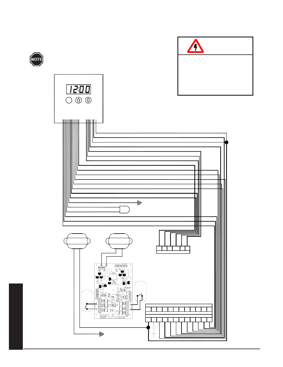
INTERNAL SYSTEM WIRING DIAGRAM - LOW VOLTAGE
The outdoor temperature sensor, room thermostat, and peak control device are connected via low voltage wiring.
System Low Voltage Wiring Diagram
HAZARDOUS VOLTAGE: Risk
of electric shock, injury, or
death. All low voltage wiring
must be segregated from line
voltage circuits in the sys-
tem.
WARNING
The "R" and "C" positions in the low voltage terminal
strip may be used as a source of 24 VAC for powering
external low voltage devices (30 VA maximum).
C
MODULE
ONE
CORE
MODULE
TWO
LIMITS
LIMITS
CORE
R
BLUE/RED
TRANSFORMER
YELLOW
BLUE
BLUE/YELLOW
75 VA
GRAY
GRAY/WHITE
PURPLE
WHITE
YELLOW
ORANGE
GREEN
BLUE/WHITE
BLACK
BROWN
BROWN
RED
M
A
P
M
M
BLUE/RED
BLUE/WHITE
ORANGE/BLUE
ORANGE
YELLOW/BLUE
YELLOW
BLUE
Terminals for Connection as a Stand Alone Furnace
Terminals for Connection with Heat Pump
Y
O
R C
R C
Y2
Y
W
G
G
OS
OS
W
W2
O2
Y2
E
SC
SC
RS
RS
NO
Peak Control Connections
RP P
COM
AP
NC
TRANSFORMER
75 VA
TX1
TX2
DISCHARGE AIR SENSOR