Warning, Heating element installation – Steffes 8188 User Manual
Page 17
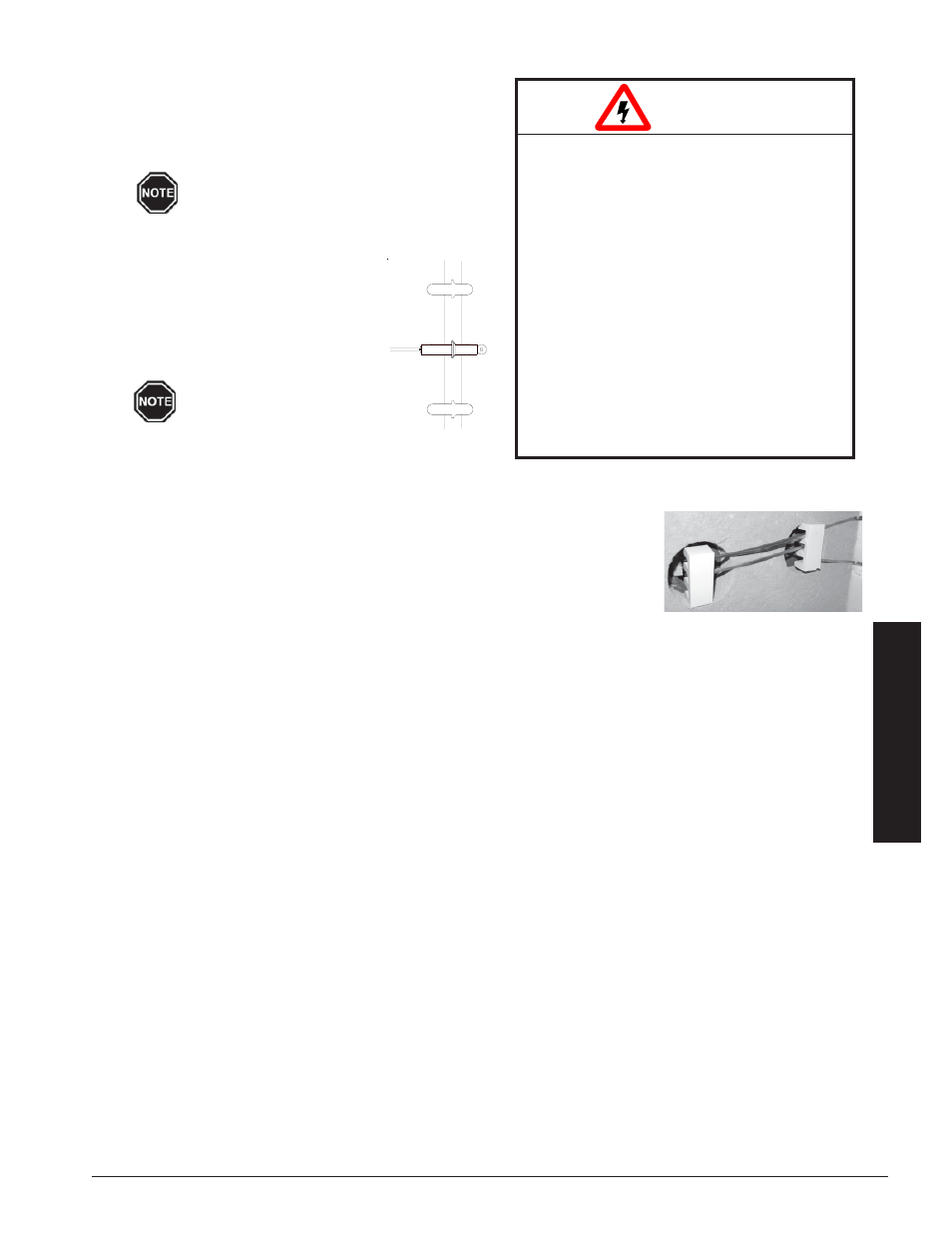
Step 3 Install element lead insulators. These ceramic
insulators MUST maintain lead wire spacings as
shown in Figure 15.
Step 4 Lower the insulation blankets back into position, one at a time. Carefully
tuck the sides of the insulation into the edges, corners, and around the
exposed portions of the heating element to ensure maximum efficiency.
Step 5 Reinstall the galvanized front panel and secure it to the system using the
screws originally removed.
Step 6 Route element harnesses through connectors, using one connector/harness until tape is centered in
connector. If installing two Storage Modules, use left hand bank of relays for left hand and right hand for
right hand. One harness per module is shorter and must be used for inside element connections.
Step 7 Attach element lead wires to element terminals. Start at the top using the appropriate color chart below.
Repeat pattern as necessary.
277/347V = Black (Top)
208/240V = Black (Top)
240V = Black (Top)
Systems
White
3phase
Red
1phase
Red
Red
Systems
Blue
Systems
Black
White
Black
Red
Blue
Red
White
Blue
Installation
FIGURE 15
FIGURE 14
HAZARDOUS VOLTAGE: Risk of electric
shock, injury, or death.
DO NOT remove the electrical panel
cover while system is energized.
Elements MUST be positioned prop-
erly to avoid short circuiting against
any surfaces within the system.
Risk of improper operation or equipment
damage. On Dual Storage Module
systems, it is critical to route the correct
harness to each of the Storage Modules.
Mis-routing of harness will result in
improper operation and equipment
damage. Make certain the harness
connected to the right side relay bank in
the electrical panel is routed to the right
side Storage Module.
WARNING
HEATING ELEMENT INSTALLATION
Step 1 After all bricks are loaded and rigid insulation boards
are in place, insert the heating elements through the
insulation, sliding them in until the cement side rails
are flush with the front side of the ceramic brick.
Make sure the elements designated as
Air Handler side elements are installed
on the Air Handler side of the Storage
Module(s).
Step 2 Route the element termination head
with ceramic insulator to the appro-
priate side of the Storage Module(s).
Insert the lead into position as
shown in Figure 14.
Element leads must never
cross each other.
T
HERM
E
LECT
I
NSTALLATION
3.08