Thermostat connections – Steffes 8188 User Manual
Page 21
Installation
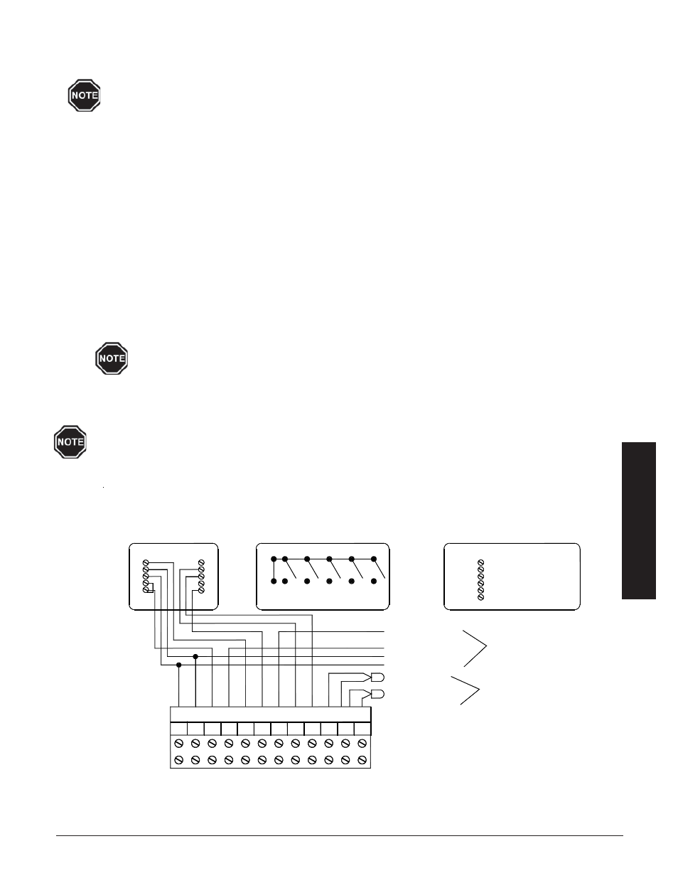
THERMOSTAT CONNECTIONS (Heat Pump Applications)
FIGURE 18
Room Sensor
Optional Freeze Protection
Outdoor Sensor
O (Reversing Valve)
Y (Compressor)
R (Low Voltage Hot)
C (Low Voltage Common)
E
G
Y2
Y
W
O O2
RS
SC
OS
Honeywell T8411R1028
Heat Pump Room Thermostat
Single Stage Cooling
A Two Stage Heating and
C
Y
W1
R
G
Thermostat Switches
G
W2
O
B
E
Y
R
L
O
W2
E
Typical Heat Pump Terminations
E - Not Used
O - To O2 on ThermElect
Y - To Y2 on ThermElect
C - To C on ThermElect
R - To R on ThermElect
W2 - Not Used
Terminals for Connection with Heat Pump
Temperature
Sensor Connections
Heat Pump
Connections
12 Position Terminal Block
C
R
Step 3
Connect the outdoor sensor wires to the “OS” and “SC” positions of the twelve (12) position low
voltage terminal block located inside the electrical compartment.
Refer to Location 10 (L010) of the Supplemental Installer's Guide to select the desired
method of charge control.
THERMOSTAT CONNECTIONS
A low voltage room thermostat is required for room temperature control with the system. Any room thermostat
used with this system must be 24 VAC. (Contact the factory for more information on the thermostats available
from Steffes.)
INSTALLING THE THERMOSTAT
Step 1 Disconnect power to the system and route low voltage wire between the thermostat and the system.
Step 2 Insulate the wall opening through which the thermostat wires run. Failure to do so may affect the accu-
racy of the thermostat.
Step 3 Attach the thermostat to a wall. If installing a mechanical thermostat or thermostat with anticipator, a
resistor kit is required (Order Item #1190015).
Step 4 Route the low voltage wire into the electrical compartment of the system through one of its low voltage
wire knockouts and to the system's twelve (12) position low voltage terminal block.
Never install any wiring in the line voltage compartment of the system unless it is rated
for line voltage.
Step 5 Refer to the Room Thermostat Connections Diagrams (Figures 18 and 19) in this manual for proper
connections with regard to the application.
Refer to Temperature Control in the Operation Section of this manual for specific operation
information.
T
HERM
E
LECT
I
NSTALLATION
3.12