Typical system line voltage wiring diagram, Appendix, Use copper or aluminum conductors rated for 75 – Steffes 8188 User Manual
Page 30: C or higher for field connection of this device, A.04 t, Neutral ground lug
Appendix
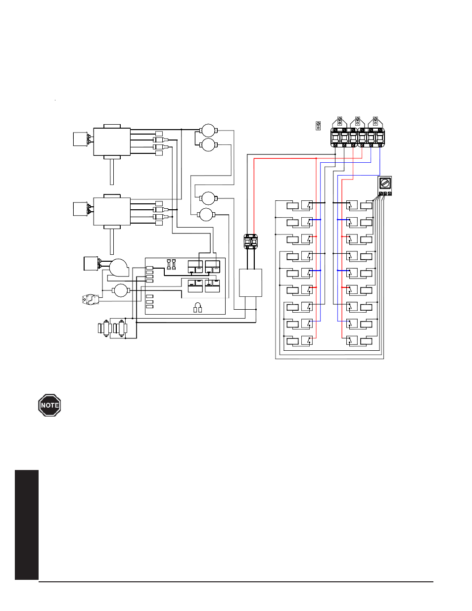
Typical System Line Voltage Wiring Diagram
277/347 3 Phase 4 Wire - 3000 CFM
8180 APPLICATION
Use copper or aluminum conductors rated for 75
o
C or higher for field connection of this device.
SUPPLY AIR BLOWER UPPER
SUPPLY AIR BLOWER LOWER
MOTOR
DAMPER
TRANSFORMER
240v / 24v
BLACK
160 °
N.C.
4uf
Cap.
BLOWER
CORE
WHITE
10uf
Cap.
MED. HIGH
MED. LOW
LOW
HIGH
COM.
COM.
Cap.
10uf
MED. LOW
MED. HIGH
HIGH
LOW
#8 Left
240 VAC Secondary
COM
COM
RESISTOR
BASE IO BOARD
BLACK/YELLOW
BLACK/YELLOW
RED
DAMPER
RESISTOR
FAN ON
RELAY
HEAT CALL
RELAY
Element Relay
Element Relay
Element Relay
#2 Left
Element
Element Relay
Element Relay
Element Relay
#4 Left
Element
#4 Left
#2 Left
#8 Left
Element
#6 Left
Element
#6 Left
Element
#1 Right
Element
#3 Right
#1 Right
#3 Right
Element
#5 Right
Element
#7 Right
#5 Right
BLACK/YELLOW
N.C.
170 °
MANUAL RESET
L2 240
BLOWER
5 Amp
L2 120
L1
1/4 Amp
NO
NO
COM
BLUE/RED
BLUE
RED
YELLOW
WHITE
BLACK
BLUE/BLACK
NO
NO
COM
Transformer
BLUE
BLUE/WHITE
N.C.
190 °
MANUAL RESET
BLACK
BLUE
YELLOW
RED
WHITE
WHITE/BLUE
190 °
ORANGE/BLACK
170 °
N.C.
N.C.
Element Relay
Element Relay
Element Relay
#11 Right
Element Relay
#13 Right
Element Relay
#15 Right
#17 Right
Element Relay
#14 Left
#12 Left
Element Relay
#10 Left
Element Relay
Element Relay
#12 Left
#10 Left
Element
#14 Left
Element
Element
Element Relay
#18 Left
#16 Left
Element Relay
Element Relay
#18 Left
#16 Left
Element
Element
Element
#9 Right
#7 Right
#9 Right
Element
#11 Right
Element
#13 Right
#17 Right
Element
#15 Right
Element
Neutral
Ground
Lug
A
PPENDIX
A.04
T
HERM
E
LECT