Electronic air filter installation, Position low voltage terminal block coding, Installation – Steffes 8188 User Manual
Page 22
I
NSTALLATION
3.13
T
HERM
E
LECT
ELECTRONIC AIR FILTER INSTALLATION
The ThermElect system is capable of being connected to an electronic air filter. Connections to the ThermElect
system are made to the bottom left relay (FAN ON) on the Base IO Relay Board inside the system's electrical
panel. This relay closes during a fan call. Refer to the Line Voltage Wiring Diagrams (Page A.04-A.05) for the
location of this relay.
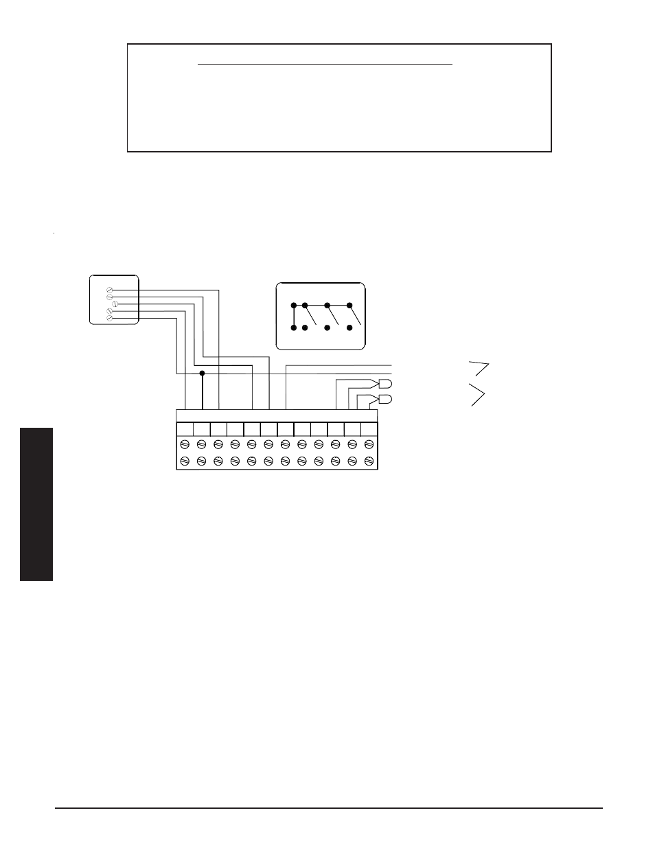
THERMOSTAT CONNECTIONS (Stand Alone Furnace Application)
FIGURE 19
W
G
Y
R
Thermostat Switches
Y (Compressor)
C (Low Voltage Common)
Outdoor Sensor
SC
OS
W2
Y Y2
G
W
R C
12 Position Terminal Block
RS
G
Y
C
R
W
Temperature
Sensor Connections
Terminals for Connection as a Stand Alone Furnace
Honeywell T8401C1015
A Single Stage Heating
and Cool Room Thermostat
Optional Freeze Protection
Room Sensor
Air Conditioner Connections
(If being used in the application)
12-Position Low Voltage Terminal Block Coding
O = Reversing Valve Input
O2 = Reversing Valve Output
E = Emergency Heat
OS = Outdoor Temperature Sensor
SC = Outdoor Temperature Sensor Common
RS = Freeze Protection Room Temperature Sensor
R = Low Voltage Hot
C = Low Voltage Common
Y = Compressor/Stage 1 Heat Call
W = Stage 2 Heat Call
Y2 = Compressor Output
G = Fan Call
Installation