Warning, Disassembling the comfort plus hydronic system – Steffes 5140 Owner & Installers Manual User Manual
Page 37
Plus fr
ont sa
ddles
and ba
ck z-B
racket
Lim
its a
nd
Rig
ht S
ide
Sad
dle
incl
ude
d
Saddles and z-brackets
can be removed if needed.
42 5/16"
Can be broken down into
individual panels.
29 3/16"
Do not remove
core limits.
28 7/8"
4140/5140
54 3/4"
4130/5130
43 3/4"
4120/5120
32 3/4"
4140/5140
56"
4130/5130
45"
4120/5120
34 1/2"
38 1/8"
29 3/16"
Including
Breakers
ALL 4100'S
45 3/4"
ALL 5100'S
48 1/4"
17 1/4"
Comfort Plus Hydronic
Appendix
A.12
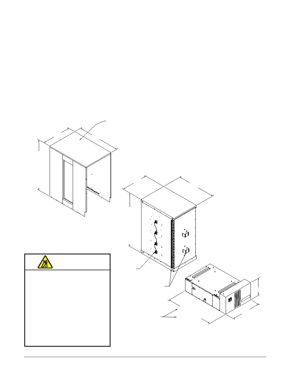
DiSaSSeMBlinG tHe coMfort PluS HyDronic SySteM
Step 1 Remove the painted front panel of the brick storage cabinet by removing the sheet metal screws along
the top, bottom, and sides of the panel. Detach by pulling the bottom of the panel forward and down.
Step 2 Remove the limit zone cover by removing the screws holding it in place.
Step 3 Remove the screws around the perimeter of the limit zone and around the bottom of the left side, right
side, and back upper panels. Disconnect limit wiring. Do not remove the limit switches.
Step 4 Remove the one or two screws in the center of the upper right side panel.
Step 5 From the back of the system, lift and remove the painted panels. (See Figure A.)
Step 6 Locate the brick core temperature sensor(s) behind the front panel and disconnect them from their
shipping position. Carefully lay the sensor(s) aside to avoid damaging them.
Step 7 Carefully rock the brick core (Figure B) to one side and lift top portion up and off the base (Figure C.)
Step 8 Move the Comfort Plus Hydronic heating system into the desired location, reassemble, and continue
with the installation instructions in this manual.
FIgUrE A
FIgUrE B
FIgUrE C
WARNING
HEAVY OBJECT WARNING: Can
cause muscle strain or back
injury.
Use lifting aids to move
system into place.
Do NOT place object, hands,
and/or body parts under the
system when lifting.
Use care to keep objects,
hands, and/or body parts
clear of system when lifting.