Installation, Warning, Placement and clearance requirements – Steffes 5140 Owner & Installers Manual User Manual
Page 11
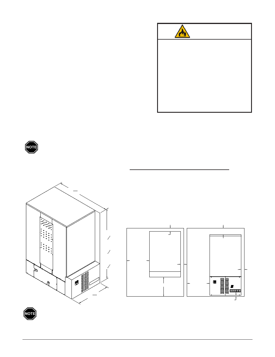
PlaceMent anD clearance reQuireMentS
The physical dimensions (Figure 1) of the Comfort Plus Hydronic
along with the clearances required (Figure 2) MUST be taken into
consideration when choosing its location within a structure. The
best installation location for this system is in a space requiring
heat, so some amount of the heating requirements can be satisfied
through static dissipation from the warm outer panels of the sys-
tem. Standby heat dissipation of up to 2.5kW can be experienced
in normal operation.
Room air should be maintained at less than
85° Fahrenheit.
If the Comfort Plus Hydronic is installed in an area where radiant
heat coming from the system is undesired or where room tempera-
tures may reach 85° Fahrenheit or greater, it is strongly recom-
mended to install a Static Heat Recovery unit or Air Handler.
Refer to pages 2.01-2.02 for information on these options.
In addition to the physical space requirements, the weight of the
Comfort Plus Hydronic must be taken into consideration when selecting the installation surface. A level concrete
floor is the best installation surface, but most well supported surfaces are acceptable. If unsure of floor load capac-
ity, consult a building contractor or architect.
Special requirements need to be considered if placing the system in a garage or other area where
combustible vapors may be present. Consult local, state, and national codes and regulations to en-
sure proper installation. An 18" stand (Order Item #1301585) is available to elevate the system.
rEQUIrED ClEArANCES
FIgUrE 2
installation
3
Comfort Plus Hydronic
Installation
3.02
Installation
3.01
Comfort Plus Hydronic
WARNING
Risk of fire. Can cause injury or death.
Violation of the clearance require-
ments or failure to provide proper
ventilation can cause improper
operation of the system. Main-
tain the placement and clearance
requirements as specified and
provide ventilation as necessary.
Moving the system after install
may result in equipment damage.
Do NOT move system from origi-
nal installed location.
MINIMUM ClEArANCE rEQUIrEMENTS
Back and Right Side = 3 inches (from combustible material)
Bottom = 1 inch clearance (from combustible material)
Top = 6 inches (from combustible material)
Front = 36 inches (for ease in servicing)
Left Side = 36 inches (for ease in servicing)
DIMENSIONS
FIgUrE 1
Minimum clearance requirements do NOT account for space needed for making electrical connec-
tions. If utilizing the Air Handler, additional space is required on the right hand side of the system.
Outle
t
Inlet
5140
68
5
8
"
5130
57
5
8
"
5120
46
5
8
"
29 3
16"
47 5
16"
Front View
TOP VIEW
3" REQUIRED
CLEARANCE
36" REQUIRED CLEARANCE
FRONT VIEW
6" REQUIRED CLEARANCE
36" REQUIRED
CLEARANCE
3" REQUIRED
CLEARANCE
P
M
M
A
36" REQUIRED
CLEARANCE
ELECTRIC THERMAL STORAGE
TEFFES
S
M
TEFFES
S
3" REQUIRED
CLEARANCE
1" REQUIRED
CLEARANCE