Installation, Rc w y – Steffes 5140 Owner & Installers Manual User Manual
Page 18
P1
C
P9
RP
2
AP
P
Aux.
Relay
Peak
Inputs
G
TH5110D
R
C
W
Y
Honeywell
R
c
(If being used in the application)
Air Conditioner Connections
C
Y
The W/E Jumper must be removed
Hydronic Heat Thermostat, Zone
Valve End Switch, or Pump Control
P8
P2
D6
To Control Board
Fid 2
D4
Blower
To Control Board
O
D3
R2
R1
D7
D5
P11
W E
Y1 Y2
Water
J4
D1
P5
J1 J2 J3
P10
P6
D2
D
A
B
C
C3
J5 J6
Blower
Speed
P4
P3
AUX
Y2 G
Y1
O
2
2
Y2
Y1
R
Air
LV Circuit Board
Comfort Plus
P7
W/
NO
NC
COM
Outdoor
Outdoor
C
R
H/E
The Y1/Y2 Jumper must be installed
RLY1
loW voltaGe electrical connectionS - rooM
tHerMoStat
A low voltage (24VAC) room thermostat is required for room temperature control with the Comfort Plus Hydronic
system. Steffes recommends using a digital thermostat. If utilizing a mechanical thermostat, a load resistor may be
necessary due to the low current draw (.01 amps) on the heat call input circuit of the Comfort Plus system. Contact
the factory for information on thermostats available from Steffes.
The Comfort Plus Hydronic system can be used in conjunction with an air conditioner or a heat pump. Refer to the
optional Air Handler (Page 2.02) and the Low Voltage Connections for Heat Pump Application Diagram (Figures
14-15), for more information on interfacing these systems with the Comfort Plus Hydronic. If multiple heat pumps
are being interfaced, contact Steffes Corporation.
Installation
3.09
Comfort Plus Hydronic
Comfort Plus Hydronic
Installation
3.10
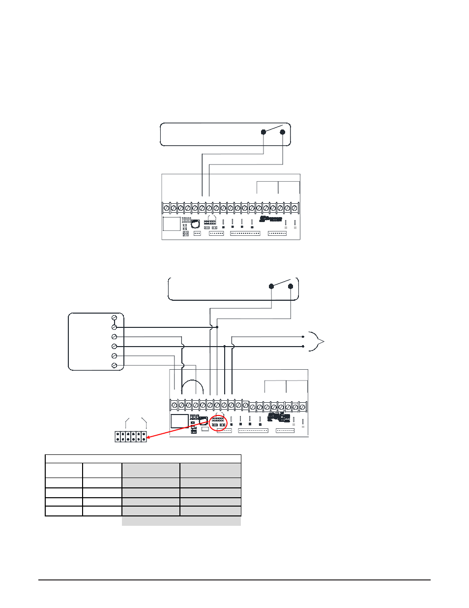
lOW VOlTAgE CONNECTIONS
HYDrONIC HEATINg SINglE ZONE SYSTEM
FIgUrE 12
STAND AlONE FUrNACE APPlICATION CONNECTIONS SHOWN FOr SINglE STAgE HEATINg
/ SINglE STAgE COOlINg (UNCONTrOllED AIr CONDITIONINg)
FIgUrE 13
* If multiple inputs are active, system will display
highest Heat Call values. "COOL" overrides all
inputs and stops all heating operations.
** Thermostat must be programmed to energize
reversing valve for cooling. If outdoor unit used re-
quires the reversing valve be energized for heating,
see Configuration Menu on pages 3.14-3.15.
IMPORTANT
Inputs
Peak
P7
LV Circuit Board
Comfort Plus
To Control Board
P10
Fid 2
RLY1
D4
D6
R2
R1
P11
D3
D7
D5
W E
Y1 Y2
Water
Air
P6
D1
P5
Blower
J3
J1 J2
J4
D2
To Control Board
P3
C
Blower
Speed
A
B
J5 J6
C3
D
P4
P2
P1
O
W/
Y1
AUX
Y2 G
Outdoor
Outdoor
Y2
R
H/E
2
Y1
C
O
2
2
RP P
R
C
P8
P9
Aux.
COM
NC
AP
NO
Relay
Hydronic Heat Thermostat, Zone
Valve End Switch, or Pump Control
A
B
C
D
W / E
Y1 / Y2
J1 J2 J3 J4
J5 J6
Blower
Speed
Single Stage Heat / Single Stage Cool **
Thermostat
Stage
Thermostat
Output
Heat Call Status
on Digital Display*
Discharge Air
Temperature Target
Hydronic
Varies
HC3
N/A
1
W
HC
2
L049
Fan Only
G
HCF
N/A
Cool
Y/G
COOL
N/A
Contractor Use Only