Appendix, Specifications – Steffes 5140 Owner & Installers Manual User Manual
Page 26
appendix
a
SPecificationS
Appendix
A.01
Comfort Plus Hydronic
Comfort Plus Hydronic
Appendix
A.02
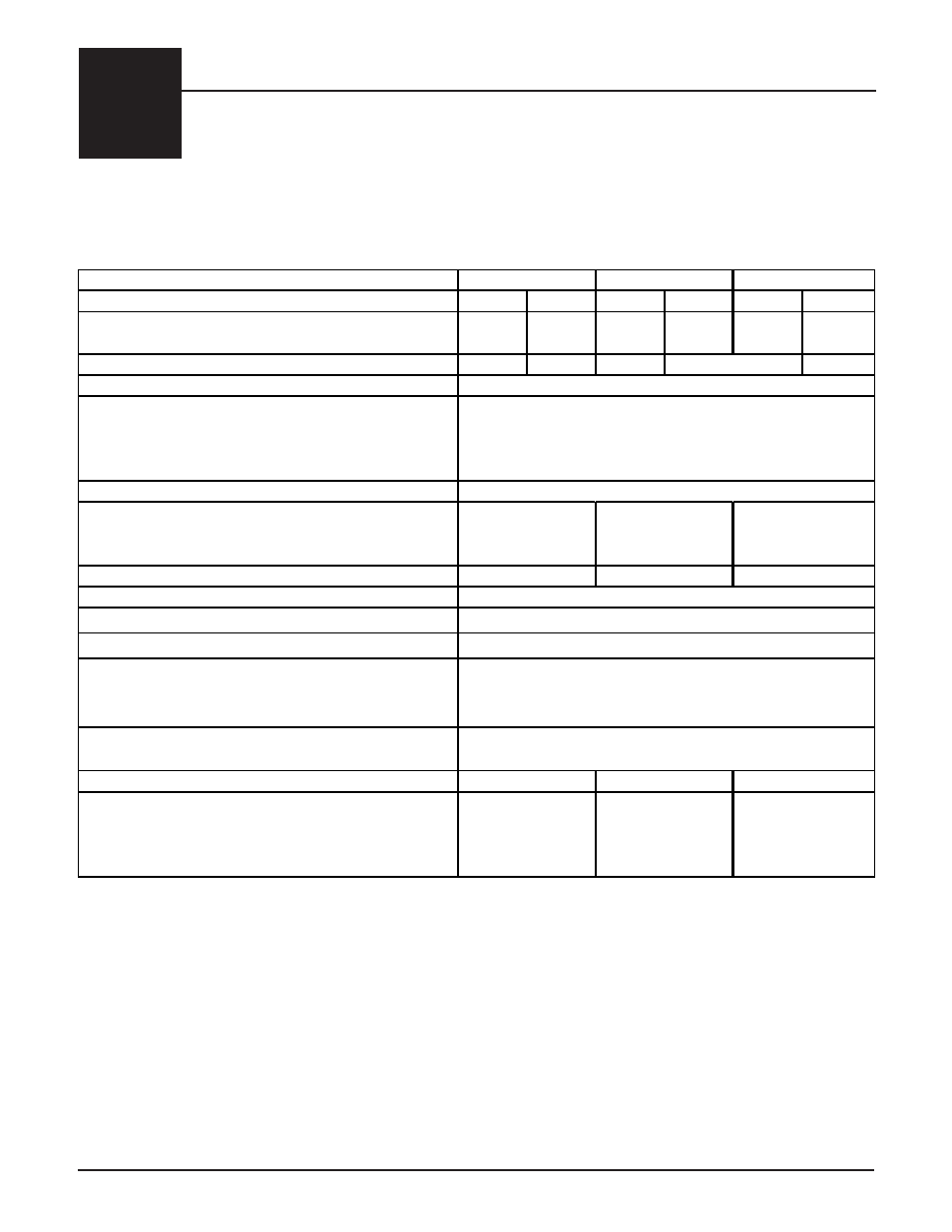
MODEl
Charging Input (kW)
19.2
24.8
28.8
37.2
38.4
45.6
Single Feed: Minimum Circuit Ampacity (240V Systems)
(Includes 25% Derate for Continuous Load)
110
140
160
204
210
248
Charging Circuits Required (240V Systems-Multiple Feed) 3-40AMP 3-50AMP 4-40AMP
4-60 AMP
Maximum Pump & Core Blower Load (240V Systems)
Element Voltage
Blowers and System Controls Voltage
Storage Capacity
kWh
BTU
System Dimensions (W x D x H in inches)
Pipe Size - Water Inlet/Water Outlet
Maximum Outlet Water Temperature
Outlet Water Temperature Selection Range
Available Maximum Working Pressure Ranges
Minimum Flow Rate (primary loop)
Approximate Installed Weight (lbs)
Number of Brick
Whole Brick
Half Brick
Total Number of Boxes
6
27
198
12
51
150
12
39
105
20 PSIG requires 30 PSI Pressure Relief Valve (Standard)
60 PSIG requires 75 PSI Pressure Relief Valve
125 PSIG requires 150 PSI Pressure Relief Valve
1 GPM per 10,000 BTU of required output at 20
o
F temperature
rise (10 GPM maximum)
3,894
3,046
2,218
50
o
F - 185
o
F
120V/240V or 120V/208V (Neutral Conductor Required)
120
180
240
426,500
614,160
818,880
29 x 46.5 x 68
29 x 46.5 x 57
29 x 46.5 x 46
1"
250
o
F
240V standard (208V and 277V optional as special factory order)
Note: The 240V element circuits can be connected to 208V
in standard configurations; however, the charging input of
the system will be derated by 25%.
5120
5130
5140
4-50 AMP
10 AMPS