Important, Line voltage wiring diagram figure 10, Installation – Steffes 5140 Owner & Installers Manual User Manual
Page 15: Comfort plus hydronic circuit breakers
Installation
3.05
Comfort Plus Hydronic
Comfort Plus Hydronic
Installation
3.06
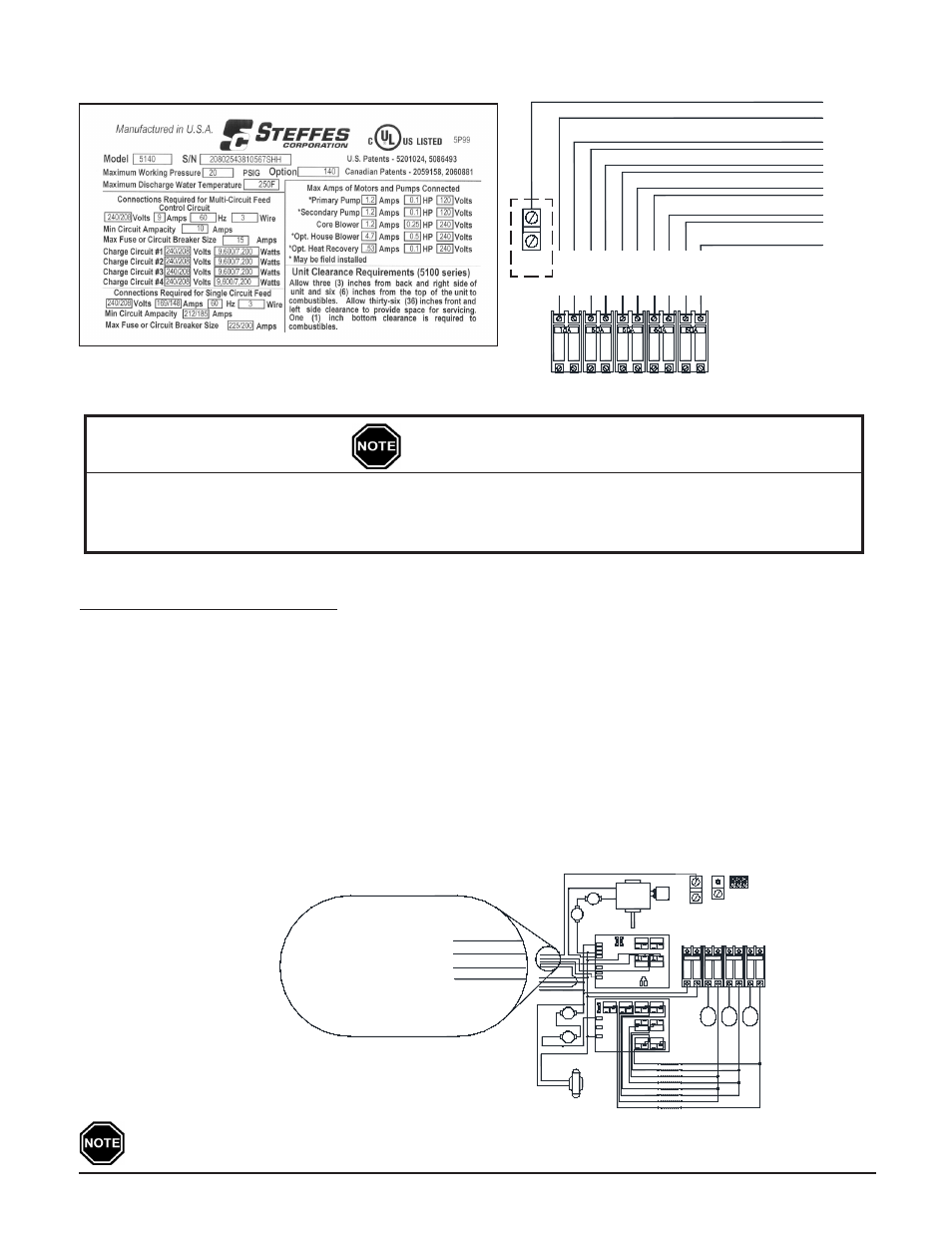
SAMPlE SYSTEM IDENTIFICATION lABEl
FIgUrE 8
JuNCTION BOx INSTAllATION
Step 1 Attach the factory supplied junction box to the left side of the Comfort Plus Hydronic system as shown
in Figure 16 (Page 3.12).
Step 2 Make connections to the primary loop pump and air handler pump inside this junction box. The red and
white wires connect to the primary loop pump and the black and white wires connect to the air handler
pump. (See Figure 10.) The maximum connected amperage on either of these circuits is 1.2 amps.
Step 3 Attach the junction box cover using the screws provided.
If utilizing the optional air handler, the orange wire can be used with the white wire to power a
secondary pump for hydronic zones.
CIrCUIT PHASINg CONNECTIONS
FIgUrE 9
NOTE: The controls
circuit MUST
include a
neutral wire.
To ensure proper operation and safety, all line voltage circuits must be segregated from low voltage
wiring in the Comfort Plus Hydronic.
To reduce electro magnetic fields associated with electrical circuits and to avoid induced voltage on
sensors and electronic devices, the circuit phases MUST be alternated as shown in Figure 9.
IMPORTANT
lINE VOlTAgE WIrINg DIAgrAM
FIgUrE 10
Comfort Plus Hydronic
Circuit Breakers
LINE 2
LINE 1
LINE 2
LINE 1
CHARGE CIRCUIT #3
CHARGE CIRCUIT #2
CHARGE CIRCUIT #1
CONTROLS CIRCUIT
CHARGE CIRCUIT #4
(MODEL 5130 and 5140 ONLY)
LINE 2
LINE 1
LINE 1
LINE 2
LINE 1
LINE 2
To Service (Breaker) Panel
NEUTRAL CONNECTION FOR CONTROL CIRCUIT
THIS MUST BE A 120/240V OR 120V/208V CIRCUIT
NEUTRAL
LUG
BLACK
COM
COM
HEATING ELEMENTS
Element 2
Element 1
Element 3
Element 4
NO
NO
75VA
240v 24v
TRANSFORMER
Element 7
Element 5
Element 6
Element 8
BLACK/YELLOW
LIMIT
WHITE/BLACK
CORE
L2 240
COM
COM
NO
NO
L2 120
RED
These wires are located on the lower left
side of the system near the inlet pipe.
75° C or higher for field connections of this device.
Use copper or aluminum conductors rated at
Wiring Diagram 240/208 Volt
5120 Line Voltage
WHITE/BLACK
RED
BLACK
Red & White To
Primary Loop Pump
(Max 1.2 AMPS)
Black & White To Air
Handler Pump (Max 1.2 AMPS)
WHITE
OR
COM
COM
NO
NO
1/4 Amp
5 Amp
225 °
N.C.
AUTO
RESET
N.C.
RESET
MANUAL
EXCHANGER
LIMITS
HIGH
BLACK
Cap.
4uf
CORE BLOWER
NEUTRAL LUG
CIRCUIT #2
CIRCUIT #3
CHARGE
CIRCUIT #1
CHARGE
CIRCUIT
CONTROLS
BLOWERS/
CHARGE
60A
60A
15A
60A
CONTROL CIRCUIT
Element
Element
Element
1,8
Relays
2,4,6
Relays
3,5,7
Relays
To
To
To
ELEMENT 1
ELEMENT 2
ELEMENT 3
ELEMENT 4
ELEMENT 5
ELEMENT 6
ELEMENT 7
ELEMENT 8
BOARD
EXPANSION
#1
GROUND
LUGS
L1
OR
WHITE
ORANGE
COM
COM
BLACK
BLACK/YELLOW
CORE
LIMIT
COM
1/4 Amp
L1
COM
NO
COM
COM
NO
NO
NO
RED
BLUE/WHITE
BLUE/BLACK
ORANGE
ORANGE
DAMPER
RESISTER
RESISTOR
SHRU
LOOP PUMP
PRIMARY
BLACK
BLUE
RED
COM.
WHITE
250 °
BLUE
BLACK/YELLOW
RED
WHITE/BLACK
BLOWER
L2 240
L2 120
NO
NO