Important, Secondary loop primary loop, Auxiliary load control – Steffes 5140 Owner & Installers Manual User Manual
Page 22: R c outdoor outdoor, Relay aux. peak inputs, Installation
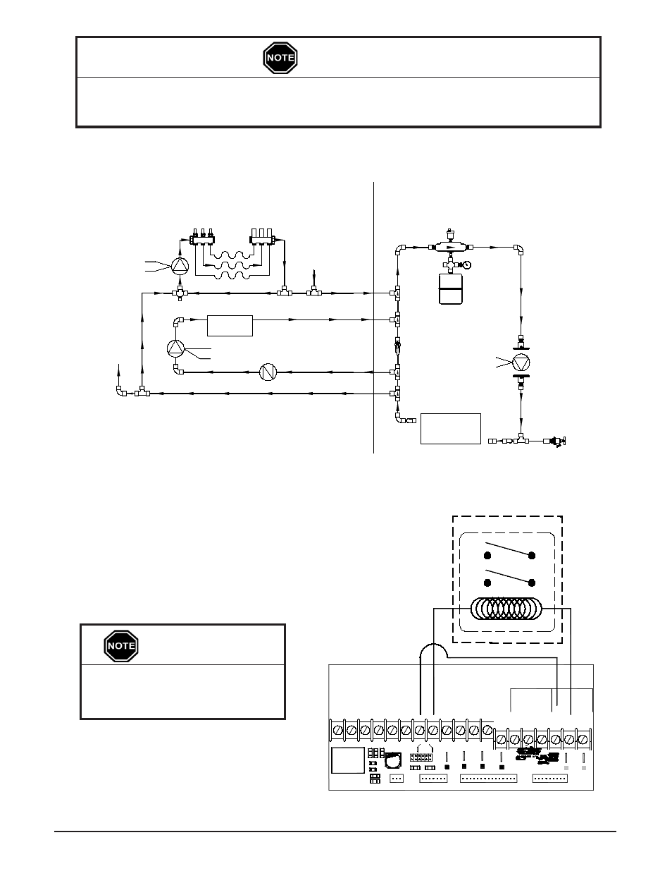
auXiliary loaD control
The Comfort Plus Hydronic system can be used
to provide control signals to other loads in the
application. To do so, connect low voltage control
wires to the "COM" and "NC" or the "COM" and
"NO" positions of the low voltage terminal block
in the electrical compartment of the Comfort Plus
Hydronic. (See Figure 19.) These contacts are
rated for 30 volts, 3 amps maximum.
IMPORTANT
Maximum external load should
not exceed 60 VA on the system's
class II transformer.
TYPICAl SYSTEM PlUMBINg
(SHOWN WITH STEFFES AIr HANDlEr)
FIgUrE 18
It is the responsibility of the installer to prevent involuntary flow of water to the air handler. Not
doing so may cause limit tripping and/or decrease heat pump efficiency. Use of a check valve,
zone valve, or other device may help prevent involuntary flow.
IMPORTANT
Installation
3.13
Comfort Plus Hydronic
Comfort Plus Hydronic
Installation
3.14
NOTE: During off-peak (charge) periods, the contact is
closed between "COM" and "NC".
TYPICAl AUxIlIArY lOAD CONTrOl
FIgUrE 19
H/E
R C
Outdoor Outdoor
COM
NC
NO
W/
D6
RLY1
To Control Board
D4
Fid 2
Blower
To Control Board
Air
R1
P10
R2
P11
D5 D7 D3
Water
Y1 Y2
W E
J4
J3
J2
J1
D2
P5
D1
P6
Speed
Blower
J6
J5
C3
D
C
B
A
P2
P3
P4
Y1
AUX
G O
Y2
Y1
O
2
Y2
2
2
P9
C
R
Comfort Plus
LV Circuit Board
P7
P1
P8
P
RP
AP
Relay
Aux.
Peak
Inputs
COM
NO
Relay Coil
Auxiliary Control Relay
Relay Contacts
NO
COM
White
Orange
White
Black
Secondary loop
Primary loop
Primary
loop Pump
High Temp
Water
5100 Air
Handler
To
Other
Zones
Mixing
Valve
This Valve Must
Be Open During
Normal Operation
From
Other
Zones
Comfort +
Hydronic
Exchanger
red
White
-
-
+
low Temp radiant Zones
CHECK
VAlVE