Important, Low voltage electrical connections - peak control, Peak control terminal connections figure 11 – Steffes 5140 Owner & Installers Manual User Manual
Page 16
loW voltaGe electrical connectionS - Peak control
Steffes ETS heating equipment may be controlled by the Power Company via a
peak control signal. This signal can be sent to the equipment using a Steffes Power
Line Carrier control system, low voltage wiring, a Steffes Time Clock Module, or
line voltage control. In applications utilizing automatic charge control, outdoor
temperature information is required and can be received via an outdoor sensor or
power line carrier control system.
The Comfort Plus Hydronic system is factory configured for low voltage peak
control and is set to charge when the utility peak control switch closes. Refer to the Configuration Menu (Pages
3.14-3.15) for information on configuring the system for the application.
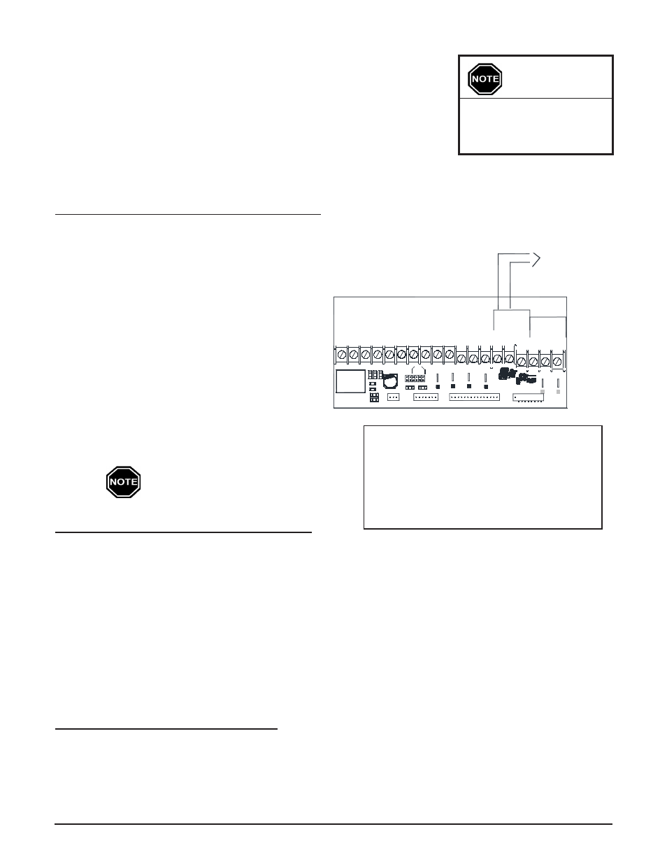
lOw VOlTAgE (HArd wIrEd) pEAk CONTrOl
If using the low voltage peak control option, the Com-
fort Plus Hydronic is direct wired to the power com-
pany's peak control switch. Field connections from the
peak control switch are made to the low voltage termi-
nal block through a low voltage knockout located on the
left side of the electrical panel.
Step 1 Route a low voltage circuit from the power
company’s load control or peak signaling de-
vice to the low voltage terminal block inside
the electrical compartment of the Comfort
Plus Hydronic system through one of its low
voltage wire knockouts. A black plastic bush-
ing is provided.
Step 2 Connect the field wiring to positions "RP"
and "P". (See Figure 11.)
To use the Comfort Plus to control other
loads, refer to Auxiliary load Control
(Page 3.13).
pOwEr lINE CArrIEr (plC) pEAk CONTrOl
The Steffes Power Line Carrier (PLC) control system has the ability to communicate with the Comfort Plus Hy-
dronic system through the existing electrical circuits in the structure. With the power line carrier option, hard wired
low voltage connections from the power company's peak signaling switch connect directly to the transmitting de-
vice. The switch signals peak control times to the transmitter, the transmitter sends the signals to the Comfort Plus
Hydronic system, which receives this information and responds accordingly.
In addition to providing peak control signals, the transmitter also provides outdoor temperature information for
automatic charge control, room temperature set back, and anticipated peak utility control signals (if applicable).
The PLC control is optional and must be ordered separately. If utilizing a PLC system, an Owner's and Installer's
manual will accompany the transmitting device. Refer to this manual for information on the installation and opera-
tion of the power line carrier control system.
TIME ClOCk MOdulE pEAk CONTrOl
The Steffes Time Clock Module is another option for providing a peak control signal to the Comfort Plus Hydronic.
It mounts inside the system’s low voltage electrical compartment and interfaces with the relay board via an inter-
face cable. Peak control times must be programmed into the system once the module is installed to enable the time
clock feature. Refer to the instructions provided with the Time Clock Module for more information on the installa-
tion and operation of this device.
low Voltage Terminal Block Coding
RP = Peak Control Input Common
P = Peak Control Input
AP = Anticipated Peak (Pre-Peak) Control Input
COM = Peak Control Output Common
NC = Peak Control Output (Normally Closed)
NO = Peak Control Output (Normally Open)
Low voltage wires
MUST never enter any
line voltage enclosure.
IMPORTANT
Installation
3.07
Comfort Plus Hydronic
Comfort Plus Hydronic
Installation
3.08
PEAK CONTrOl TErMINAl CONNECTIONS
FIgUrE 11
P9
Aux.
COM
NC
AP
NO
Relay
P8
O
W/
Y1
AUX
Y2 G
Outdoor
Outdoor
Y2
R
H/E
2
Y1
C
O
2
2
RP P
R
C
P1
Inputs
Peak
P7
LV Circuit Board
Comfort Plus
To Control Board
P10
Fid 2
RLY1
D4
D6
R2
R1
P11
D3
D7
D5
W E
Y1 Y2
Water
Air
P6
D1
P5
Blower
J3
J1 J2
J4
D2
To Control Board
P3
C
Blower
Speed
A
B
J5 J6
C3
D
P4
P2
Dry Contact Peak
Control Switch