Two stage heat pump application figure 15, Single stage heat pump application figure 14, Comfort plus hydronic installation – Steffes 5140 Owner & Installers Manual User Manual
Page 19: W - not used, Outdoor sensor
The W/E Jumper must be removed
The Y1/Y2 Jumper must be removed
Inputs
Peak
P7
LV Circuit Board
Comfort Plus
To Control Board
P10
Fid 2
RLY1
D4
D6
R2
R1
P11
D3
D7
D5
W E
Y1 Y2
Water
A
ir
P6
D1
P5
Blower
J3
J1
J2
J4
D2
To Control Board
P3
C
Blower
Speed
A
B
J5
J6
C3
D
P4
P2
P1
O
W/
Y1
AUX
Y2 G
Outdoor
Outdoor
Y2
R
H/E
2
Y1
C
O
2
2
RP P
R
C
P8
P9
Aux.
COM
NC
AP
NO
Relay
Honeywell TH5320D
Aux
L Y2
G
C
O/B
Hydronic Heat Thermostat, Zone
Valve End Switch, or Pump Control
R
Y R
c
C - Low Voltage Common
Outdoor Sensor
O - Reversing Valve
R - Low Voltage Hot
To Heat Pump
Y1 - Compressor
Y2 - Compressor Stage 2
W - Not Used
H/E
R C
Outdoor
Outdoor
COM
NC
NO
W/
D6
RLY1
To Control Board
D4
Fid 2
Blower
To Control Board
A
ir
C3
P10
R1
R2
P11
D5 D7 D3
Water
Y1 Y2
W E
D2
J3
J2
J1
P5
D1
J4
P6
P4
Speed
Blower
J6
J5
C
B
A
D
P2
P3
Y1
AUX
O
G
Y2
Y1
2
Y2
2
2
O
C
R
Comfort Plus
LV Circuit Board
P7
W - Not Used
AP
P
RP
Peak
Aux.
Inputs
Relay
The Y1/Y2 Jumper must be installed
Honeywell TH5220D
Aux
E
L
C
G O/B
R
Y
R
c
Hydronic Heat Thermostat, Zone
Valve End Switch, or Pump Control
C - Low Voltage Common
R - Low Voltage Hot
O - Reversing Valve
Y - Compressor
To Heat Pump
Outdoor Sensor
The W/E Jumper must be removed
P9
P1
P8
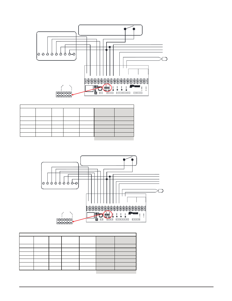
Comfort Plus Hydronic
Installation
n
3.10
TWO STAGE HEAT PUMP APPLICATION
FIGURE 15
*
If multiple inputs are active, system will
display highest Heat Call values. "COOL"
overrides all inputs and stops all heating
operations.
** Systems built before 1/1/2011 are con-
fi gured for 50% airfl ow in Stage 1. For
more information, refer to Instruction
#1200601-High Speed Stage 1 Relay
Installation.
*** Thermostat must be programmed to
energize reversing valve for cooling. If
outdoor unit used requires the reversing
valve be energized for heating, see Con-
fi guration Menu on pages 3.14-3.15.
IMPORTANT
SINGLE STAGE HEAT PUMP APPLICATION
FIGURE 14
* If multiple inputs are active, system will
display highest Heat Call values. "COOL"
overrides all inputs and stops all heating
operations.
** Thermostat must be programmed to energize
reversing valve for cooling. If outdoor unit
used requires the reversing valve be ener-
gized for heating, see Confi guration Menu on
pages 3.14-3.15.
IMPORTANT
A
B
C
D
W / E
Y1 / Y2
J1
J2
J3
J4
J5
J6
Blower
Speed
A
B
C
D
W / E
Y1 / Y2
J1
J2
J3
J4
J5
J6
Blower
Speed
Single Stage Heat Pump with Auxiliary Heat / Single Stage Cool **
Thermostat
Stage
Thermostat
Output
Heat
Pump
Stage
ECM Board
Output to
Heat Pump*
% of
Selected
CFM
Heat Call
Status on
Digital Display*
Discharge Air
Temperature
Target
1
Y/G
1
R/Y1
2
100%
HC1
L048/C010
Aux
Aux/Y/G
1
R/Y1
2
100%
HC2
L049
Fan
G
0
R
400 cfm
HCF
N/A
Cool
Y/G/O
1
R/Y1
2
/O
2
100%
COOL
N/A
Hydronic
Varies
N/A
N/A
OFF
HC3
N/A
Contractor Use Only
Two Stage Heat Pump with Auxiliary Heat / Two Stage Cool ***
Thermostat
Stage
Thermostat
Output
Heat
Pump
Stage
ECM Board
Output to Heat
Pump*
% of Selected
CFM
Heat Call
Status on
Digital Display*
Discharge Air
Temperature
Target
1
Y/G
1
R/Y1
2
50% or 70%**
HC1
L048/C010
2
Y/Y2/G
2
R/Y1
2
/Y2
2
100%
HC1
L048/C010
3
Aux/Y/Y2/G
2
R/Y1
2
/Y2
2
100%
HC2
L049
Fan
G
0
R
400 cfm
HCF
N/A
Cool 1
Y/G/O
1
R/Y1
2
/O
2
50% or 70%**
COOL
N/A
Cool 2
Y/Y2/G/O
2
R/Y1
2
/Y2
2
/O
2
100%
COOL
N/A
Hydronic
Varies
N/A
N/A
OFF
HC3
N/A
Contractor Use Only