Wiring diagram – Panasonic CQ-DF201U User Manual
Page 24
Attention! The text in this document has been recognized automatically. To view the original document, you can use the "Original mode".
Cautions:
• This product is designed to operate of a 12 volt, negative ground battery system,
e To prevent damage to the unit, be sure to follow the connection diagram below.
© Remove approx. У/' (5 mm) of protective covering from the ends of the leads before connecting.
© Do not insert the power connector into the unit until the wiring is completed,
о Be sure to insulate any exposed wires from a possible short-circuit from the car chassis. Bundle all cables
and keep cable terminals free from touching any metal parts,
о Remember, if your car has a drive computer or a navigation computer, the data of its memory may be
erased when the battery terminals are disconnected,
Supplied hardware
No.
Item
Q’ty
(D
Power connector
1
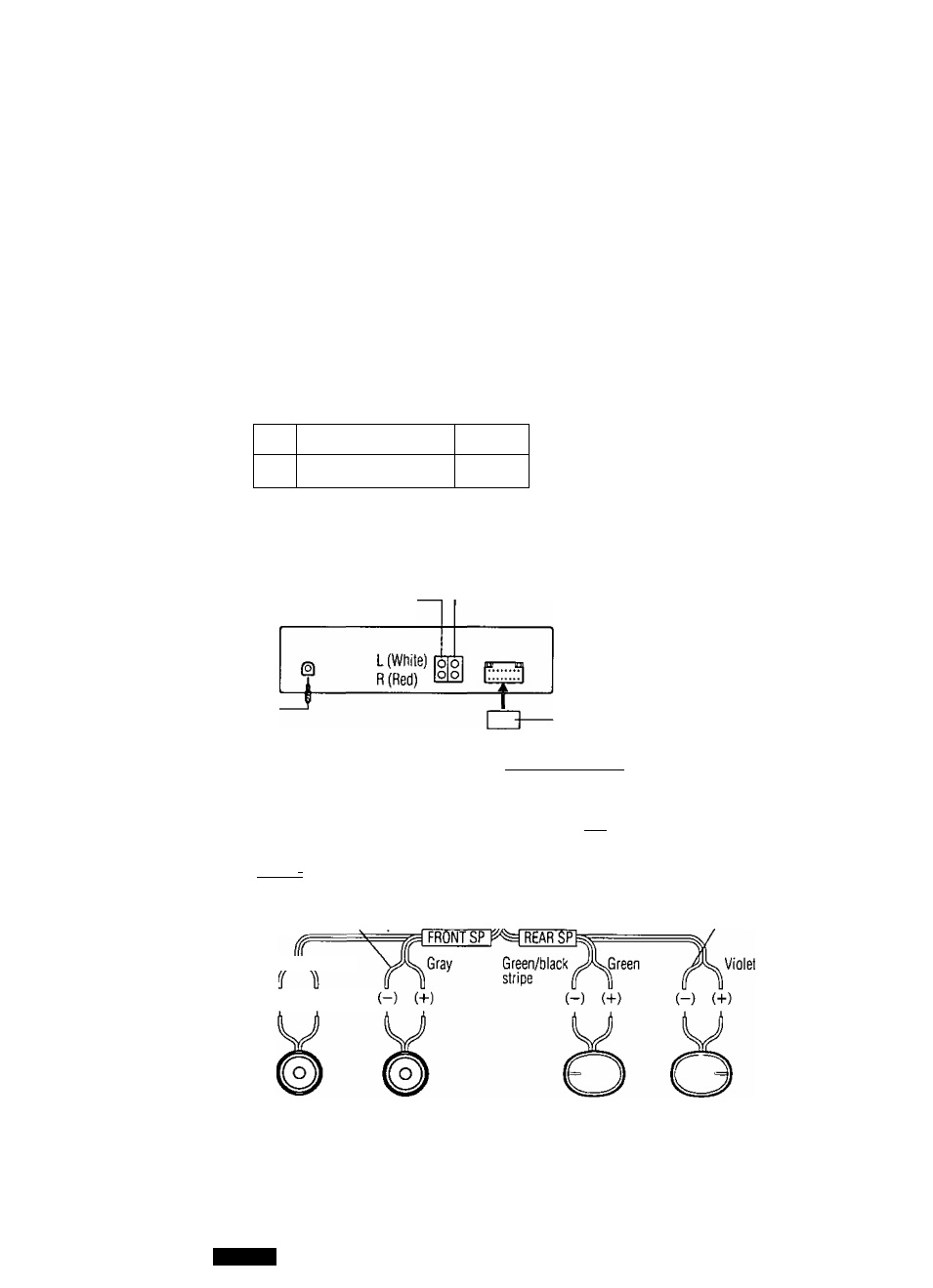
□ Wiring Diagram
Preamp out connector (front)
Preamp out connector (rear)
Antenna
(1) Power connector
Ground lead
Dark blue
To a clean, bare metallic part of car chassis.
Motor antenna t-------r
relay control
Moves antenna up and down.
Grsy/black stripe
White/black stripe White
(-) (-«-)
iN BATTERY 15A>r^^
Yellow
Fuse (15 A)
ACC I—C
Red
Resistor (1 kO)
Speaker lead
Battery lead
To the car battery,
continuous +12VDC
Power lead
To ACC power,
+12VDC
Violet/black stripe
Left speaker
(Front)
Right speaker
(Front)
Left speaker
(Rear)
Right speaker
(Rear)
24
m
DR20ilU