Electrical connections, Wiring diagram – Panasonic CQ-C8300U User Manual
Page 66
Attention! The text in this document has been recognized automatically. To view the original document, you can use the "Original mode".
Electrical Connections
Caution:
• This product is designed to operate with a 12 V
DC, negative ground battery system.
• To prevent damage to the unit, be sure to follow
the connection diagram below.
• Remove approximately V/' (5 mm) of protective
covering from the ends of the leads before
connecting.
• Do not insert the power connector into the unit
until the wiring is completed.
• Be sure to insulate any exposed wires from
a possible short-circuit from the car chassis.
Bundle all cables and keep cable terminals free
from touching any metal parts.
• Remember, if your car has a drive computer or
a navigation computer, the data of its memory
may be erased when the battery terminals are
disconnected.
J
Wiring Diagram
Accessory used for wiring
No.
Item
Q’ty
(D
Power connector
1
CQ-C840QU
DC/DC Converter *
External amplifier control power lead
(max. 500 mA)
This lead is for connection to the power amplifier.
CQ-C8300U
CQ-C8200U
CQ-C8Í00U
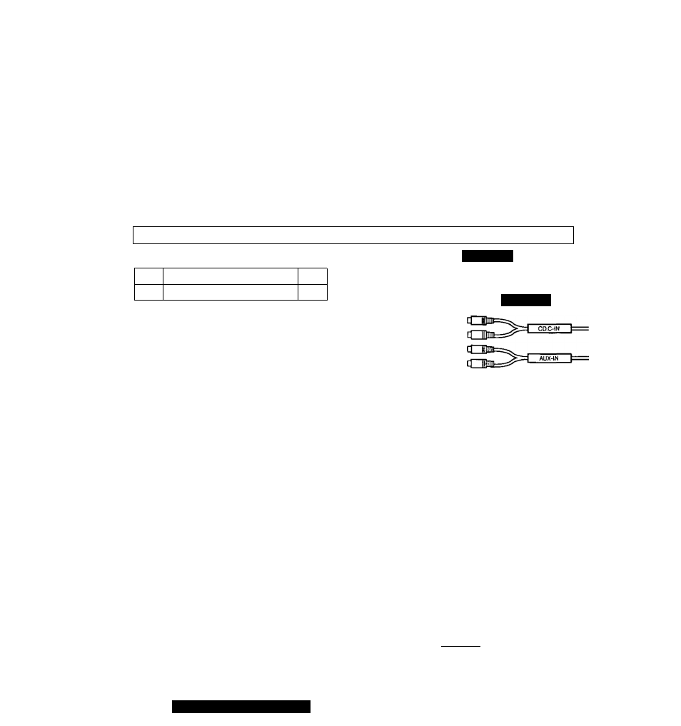
CD changer
R (red)
input cord
L (white)
AUX
R (red)
input cord
L (white)
Note:
• This lead is used for power control when an external power amplifier is
connected. The power supply of a power amplifier will be activated when
turning on the power of this unit.
(BlueMhite stripe)
Dual CD changer control lead ^
Note:
• Insulate this lead with vinyl tape when you do not connect it.
(BrownAvhite stripe)
Antenna control lead ^
(to motor antenna) (max. 500 mA)
This lead is not intended for use with switch actuated power antenna.
(Blue)
Note:
• The power antenna extends automatically
when the AM/FM radio mode is
selected.
ACC power lead ^
To ACC power, -i-12 V DC.
=Ç=c
ACC
(Red)
Battery lead ^
To the car battery, continuous +12 V DC.
BATTERY 15J
fVelJoiv)
Ground lead
To a clean, bare metallic part of the car chassis.
(Black)
66
CQ-C8400/8300/8200/8100U