Rear view – Panasonic WV-CM143 User Manual
Page 5
Attention! The text in this document has been recognized automatically. To view the original document, you can use the "Original mode".
10. Bright Control (BRIGHT)
Turn this control clockwise to increase the picture
brightness and turn this control counterclockwise to
decrease the picture brightness.
11. Bright Subcontrol
12. Contrast Control (CONTRAST)
Turn this control clockwise to increase the picture con
trast and turn this control counterclockwise to
decrease the picture contrast.
13. Contrast Subcontrol (CONTRAST)
14. Picture Adjustment (PICTURE)
Turn this control clockwise for sharp picture and turn
this control clockwise for soft picture.
15. Audio Controi (AUDIO, MIN/MAX)
Turn this control clockwise to increase the audio level
and turn this control counterclockwise to decrease the
audio level,
16. Sequence / Setup Selection Switch
(SEQUENCE/SETUP)
Press this switch more than 2 seconds to display the
Set Up menu.
17. Camera Selection Switch (1)/ Up Switch ( A )
18. Camera Selection Switch (2) / Down Switch ( T )
19. Camera Selection Switch (3) / Left Switch (<^)
20. Camera Selection Switch (4) / Right Switch (►)
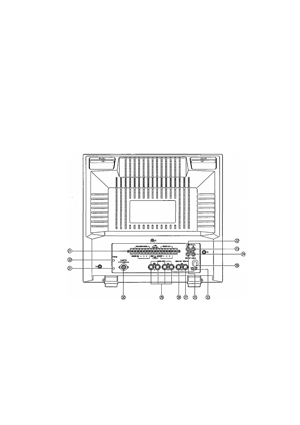
REAR VIEW
21. External Control Connection Terminals
RECOVER
When the picture of the camera is selected by the
signal of Spot Monitor Control In, the monitor only
displays the picture of the selected camera.
To reset the picture of the selected camera and to
set to the sequence operation for the Color CCTV
System, use the reset signal from the time lapse
VTR.
SPOT MONITOR CONTROL IN
The terminals of the Spot Monitor Control In are
used to connect the intercom or alarm sensors for
the spot monitoring by short circuit between termi
nal 1,2, 3 or 4 and ground.
When the Camera Extension Unit is used, the
same spot monitoring are proceeded for terminal
5, 6 and 7 of the camera extension unit.
If the terminal 1 is shorted to the ground by inter
com or alarm sensors, the camera No.1 is select
ed and its picture is observed as spot monitoring.
The picture of the camera No.2, 3, 4, 5, 6, or 7
can be observed as the same way when the
Camera Extension Unit is used.
Note: The voltage of short circuit for terminal should be
0 - 0.2 volt when the intercom or alarm sensor is
activated.
ALARM CONTROL OUT
The terminals of the Alarm Control Out are used to
connect the buzzer or chime for sounding when
the terminals of the Spot Monitor Control In is
shorted to ground by intercom or alarm sensor.
-3-