Connection with the vtr, V. r7 – Panasonic WV-CM143 User Manual
Page 16
Attention! The text in this document has been recognized automatically. To view the original document, you can use the "Original mode".
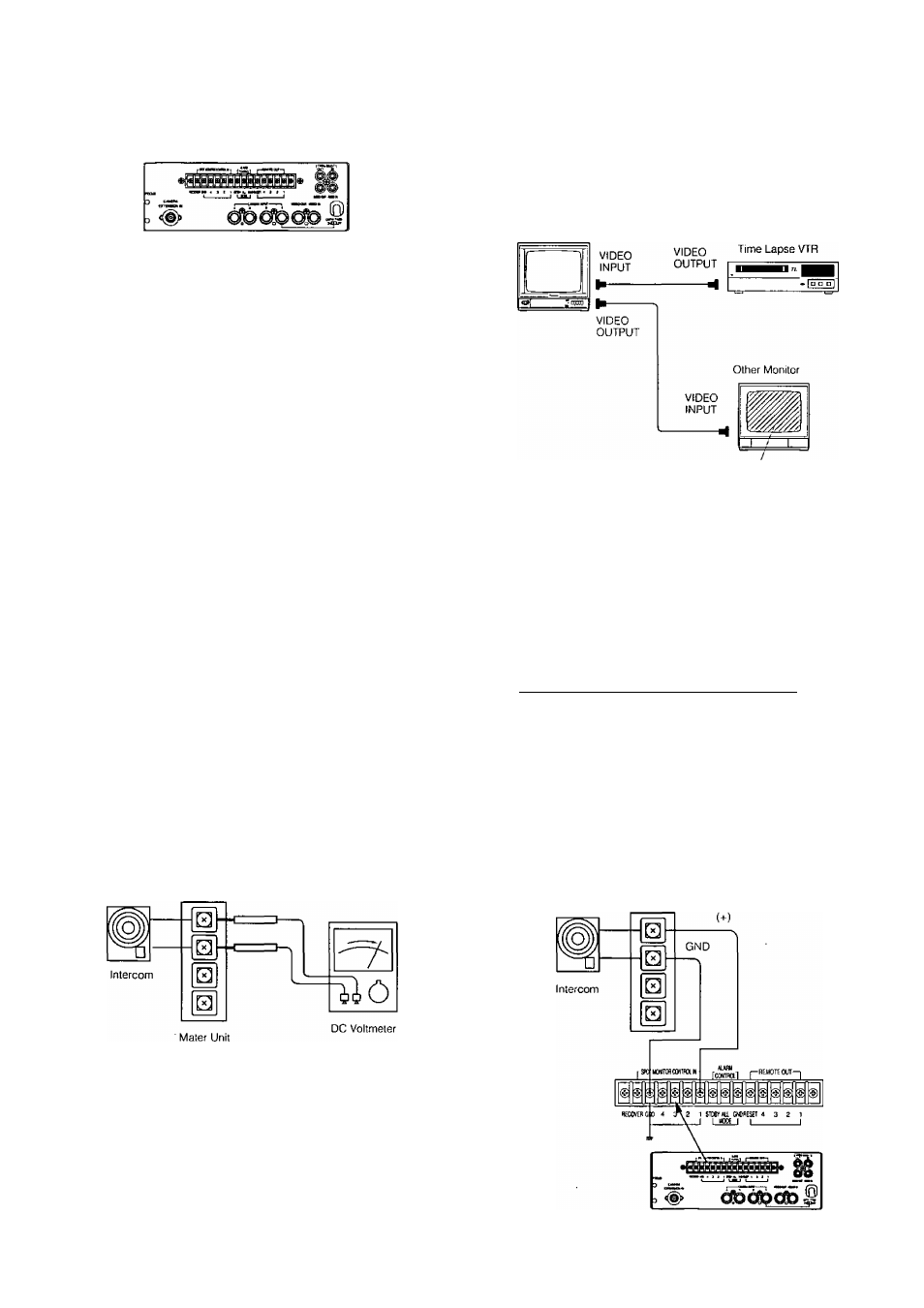
Connection with the VTR
Color Monitor WV-CM143
VIDEO
OUTPUT
BNC Connector
Coaxial Cable
Time Lapse VTR
Connect a coaxial cable between the video output signal of
the VTR and the VIDEO IN of this monitor.
Note: Avoid the following connection when monitoring the
playback picture of VTR.
Color Monitor
WV-CM143
Noise
Connection with the Intercom and Alarm Sensors/Switches
The wiring for intercom system and alarm sensor
/switches should be two wires.
The power source for intercom system and alarm sen-
sors/switches should be less than DC 12V.
When the intercom or alarm sensor/switch is activated,
the line voltage for intercom or alarm sensor/switch
should be DC 0-0.2V.
Power source level
Less than 12V DC
V. r7
Calling period or activated
period (less than 0.2V)
OV
There is a limitation for the wiring length among the inter
com system, alarm sensors system, optional units and
video monitor.
For example, the wiring length for intercom system is as fol
lows ;
Wires
(mm/Q‘ty)
Equivalent
AWG SWG
Maximum
Wiring length
0.18/12
22
23
150m
0.18/20
20
21
250m
0.18/30
18
19
400m
0.18/50
16
17
600m
AWG: American Wire Gauge
SWG; British Legal Standard Wire Gauge
The polarity for the intercom system and the Spot Monitor
Control In of the monitor should be matched. Make sure the
polarity of the intercom system by tester (meter).
Mater Unit
-14-