Satellite High Tech 2 User Manual
Page 5
- 5 -
P/N 18968 REV, B
4/07
11. Install roof on unit: “STOP AT THIS POINT: IF INSTALLING KIT-SOLAR LIGHT REMOTE #19257
REFER TO INSTRUCTIONS SOLAR LIGHT REMOTE #19283 INCLUDED IN KIT”
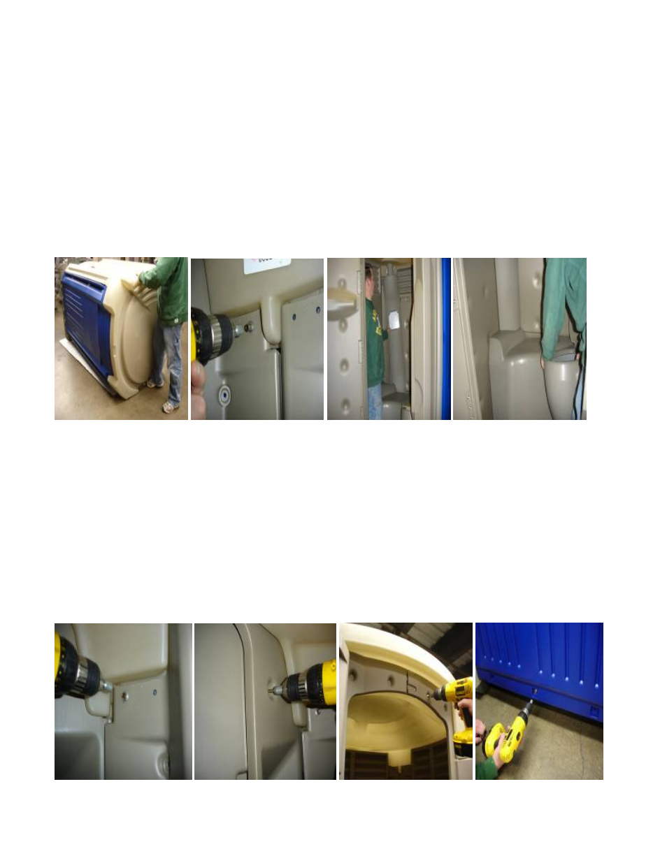
Place roof #18938 on top of unit. (See pic. P) Tip unit onto base, one person holds roof in place and lifts while
Other person pulls on base to tip unit upright.
12. Fasten roof to panels: Start in rear left corner where vent pipe hole is located. Install screws
#14 x 1-1/2" #13860 (4) with 3/8" hex nut driver bit through holes in panel into cored holes in roof #18938,
may need to pull down on roof through vent pipe hole in roof to locate cored holes in roof. (See pic.Q)
“STOP AT THIS POINT: IF ASSEMBLING AN UPGRADE / FLUSH UNIT SEE INSTRUCTIONS #19403
AND REFER TO PICTURES 1-3 TO CONNECT OUTLET HOSE FROM PUMP TO BOWL”
13. Install vent pipe: To install vent pipe #18940 in roof #18938. Pull tank back from rear panel approximately 6",
slide vent pipe behind tank, push round end of vent pipe up into opening in roof. (See pic. R) To seat vent pipe
in tank #18939, move tank back into position on base lifting on right side of tank so the bottom of the vent pipe
seats in tank opening, top left corner of the tank [may need to rock tank back and forth]. (See pic. S)
P Q R S
14. Finish fastening roof to panels: in rear right corner on inside of unit. Use screws #14 x 1-1/2" P/N 13860 (4)
with 3/8” hex nut driver bit, same procedure as fastening roof to panels in the rear left corner. [Note: may need
person outside unit to pull down on roof to locate & install screws in cored holes on inside of roof]. Fasten roof to
panels in front corners of unit, inside of unit using screws #14 x 1-1/2" #13860 (4 total, 2 per side) with 3/8"
hex nut driver bit. (See pic. T)
15. Fasten roof to front: from inside unit using screws #14 x 1-1/2" #13860 (2) with 3/8 nut driver bit in dimples
located in recessed areas left & right door frame. (See pic. U) Fasten roof to door frame from outside unit using
screws #14 x 1-1/2" #13860 (4) with 3/8" hex nut driver bit in 4 holes at the top of door frame. (See pic. V)
16. Fasten rear panel to base: with screws 1/4 x 3/4" #19496 (3) through holes at bottom of panel into alum
inserts in base.(See pic.W) [Note: it is very important that all the screws be started with a Phillips
screwdriver first and then tighten up with a 3/8 nut driver bit]. (If holes in panels don’t line up to allow
easy starting with phillip screwdriver elongate hole in panel sideways until they align easily.)
T U
V W