Pilz PSEN ma1.4p-51/PSEN ma1.4-10mm/ 1unit User Manual
Page 3
- 3 -
Verdrahtung
492354955
Beachten Sie:
`
Angaben im Abschnitt „Technische Daten“
unbedingt einhalten.
`
Berechnung der max. Leitungslänge I
max
im
Eingangskreis:
R
lmax
= max. Gesamtleitungswiderstand
(s. techn. Daten)
R
l
/ km = Leitungswiderstand/km
`
Beachten Sie bei Einsatz von Auswertegerä-
ten mit rückfallverzögerten Kontakten:
– Verzögerungszeit
≤
30 s: die rückfallverzö-
gerten Kontakte genügen den Anforderun-
gen der Kategorie 3 gemäß EN 954-1 bzw.
den Anforderungen an PDF mit Einfehlersi-
cherheit (PDF-S).
– Verzögerungszeit
≥
30 s: die rückfallverzö-
gerten Kontakte genügen den Anforderun-
gen der Kategorie 1 gemäß EN 954-1 bzw.
den Anforderungen an PDF mit Zuverläs-
sigkeit durch besonderes Design (PDF-D).
`
Überprüfen Sie in folgenden Fällen von Inbe-
triebnahme die Funktion Querschlusserken-
nung:
– Bei Auswertegeräten mit Versorgungs-
spannung DC: Gesamtleitungswiderstand
≥
15 Ohm pro Kanal
– Bei Auswertegeräten mit Versorgungs-
spannung AC: Gesamtleitungswiderstand
≥
25 Ohm pro Kanal
– Wie Sie die Querschlussprüfung durchfüh-
ren müssen, entnehmen Sie der entspre-
chenden Bedienungsanleitung des
Auswertegeräts.
Wiring
Please note:
`
Information given in the “Technical details”
must be followed.
`
Calculation of the max. cable runs l
max
in the
input circuit:
R
lmax
= max. overall cable resistance (see
Technical details)
R
l
/ km = cable resistance/km
`
When using evaluation devices with delay-on
de-energisation contacts, please note:
– Delay time
≤
30 s: Delay-on de-energisation
contacts satisfy the requirements of cate-
gory 3 in accordance with EN 954-1 and
the requirements of a PDF with single-fault
tolerance (PDF-S).
– Delay time
≥
30 s: Delay-on de-energisa-
tion contacts satisfy the requirements of
Category 1 in accordance with EN 954-1
and the requirements of a PDF with de-
signed reliability (PDF-D).
`
In the following commissioning cases, check
the function that detects shorts across con-
tacts:
– On evaluation devices with DC supply
voltage: Overall cable resistance
≥
15 Ohms per channel
– On evaluation devices with AC supply volt-
age: Overall cable resistance
≥
25 Ohms
per channel
– For details of how to perform the test for
shorts across the contacts, please refer to
the operating manual for the relevant eval-
uation device.
Câblage
Important :
`
Tenez compte impérativement des données
indiquées au chapitre "Caractéristiques
techniques".
`
Calcul de la longueur de câble max. I
max
sur
le circuit d'entrée :
R
lmax
= résistance max. de l'ensemble du
câblage (voir les caractéristiques techni-
ques)
R
l
/km = résistance du câblage/km
`
En cas de mise en œuvre d'appareils de con-
trôle avec contacts temporisés à la retom-
bée, il faut tenir compte des indications
suivantes :
– Temporisation
≤
30 s : les contacts tempo-
risés à la retombée satisfont aux prescrip-
tions de la catégorie 3 selon l'EN 954-1, et/
ou aux prescriptions des PDF avec sécuri-
té de défaut unique (PDF-S).
– Temporisation
≥
30 s : les contacts tempo-
risés à la retombée satisfont aux prescrip-
tions de la catégorie 1 selon l'EN 954-1, et/
ou aux prescriptions des PDF avec une
fiabilité obtenue grâce à un design particu-
lier (PDF-D).
`
Vérifiez dans les cas suivants de mise en ser-
vice la fonction de détection des courts-
circuits :
– pour les appareils de contrôle avec ali-
mentation DC : Résistance de l'ensemble
du câblage
≥
15 ohms par canal
– pour les appareils de contrôle avec ali-
mentation AC : Résistance de l'ensemble
du câblage
≥
25 ohms par canal
– vous trouverez dans la notice d'utilisation
de l'appareil de contrôle comment exécu-
ter le contrôle des courts-circuits.
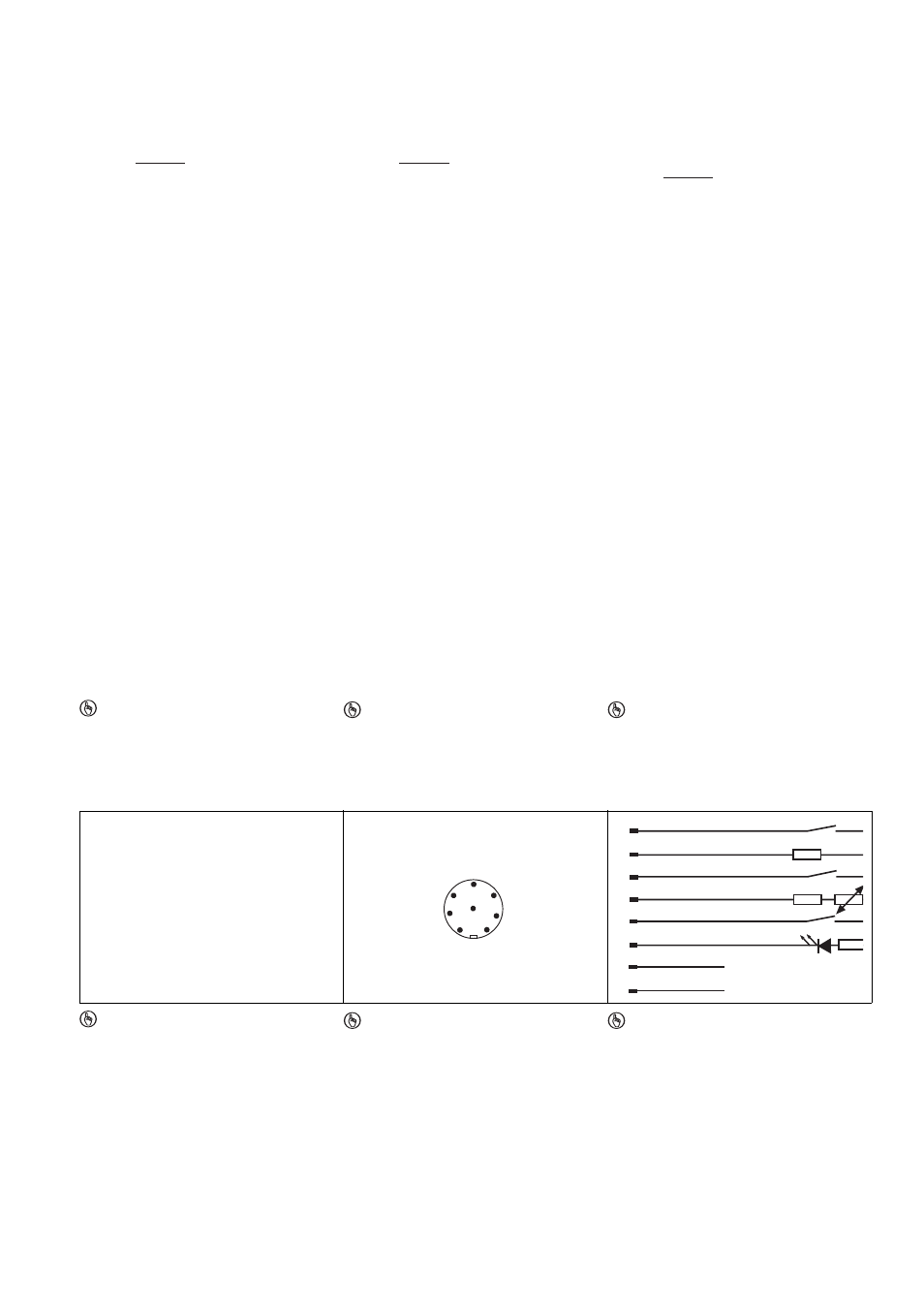
Anschlüsse
Connections
Raccordements
Anschlussbelegung
Terminal assignment
Repérage des broches
777658251
WICHTIG
Die Farbkennzeichnung für die Anschlus-
sleitung gilt nur für die als Zubehör erhältli-
chen Kabel von Pilz.
Der Sicherheitsschalter ist in unbetätigtem Zu-
stand dargestellt.
NOTICE
The colour marking for the connection lead
only applies for the cable that Pilz supplies
as an accessory.
The safety switch is shown in an unoperated
condition.
IMPORTANT
Le marquage de couleur du câble de rac-
cordement est uniquement valable pour les
câbles Pilz disponibles en tant qu'acces-
soires.
Le capteur de sécurité est représenté en posi-
tion de repos.
Belegung des 8-pol. M8-Stiftsteckers/Assign-
ment of the 8-pin M8 male connector/Repéra-
ge du connecteur mâle M8 à 8 pôles
807945483
WICHTIG
Der Hilfskontakt mit LED
`
darf mit PNOZ X-Geräten nur mit Versor-
gungsspannung bis 24 V DC betrieben
werden
`
ist mit PNOZ X-, PNOZelog- und
PNOZmulti-Geräten nicht in Reihe
schaltbar
NOTICE
The auxiliary contact with LED
`
May only be operated with a supply volt-
age up to 24 VDC on PNOZ X units
`
May not be connected in series with
PNOZ X, PNOZelog and PNOZmulti
units
IMPORTANT
Le contact d'information avec LED
`
ne doit être utilisé, pour les appareils
PNOZ X, qu'avec une alimentation jus-
qu'à 24 V DC
`
ne peut pas être monté en série avec les
appareils PNOZ X, PNOZelog et
PNOZmulti
R
lmax
R
l
/ km
I
max
=
R
lmax
R
l
/ km
I
max
=
R
lmax
R
l
/ km
I
max
=
1
2
3
4
8
5
6
7
weiß/white/blanc
braun/brown/marron
blau/blue/bleu
gelb/yellow/ambre
rot/red/rouge
grün/green/vert
6
3
1
4
2+
7
NC
NC
5
8
grau/grey/gris
rosa/pink/rose