Justage, Anschlüsse, Adjustment – Pilz PSEN 2.1b-20/8mm/10m/ 1switch User Manual
Page 2: Connections, Ajustement, Raccordement
- 2 -
Sicherheitsschalter und Betätiger
• von Eisenspänen fernhalten
• keinen starken Magnetfeldern aussetzen
• keinen starken Stößen oder Schwingun-
gen aussetzen
• nicht als Anschlag benutzen
• nur für feste Verkabelung
Justage
• Der Sicherheitsschalter darf nur mit dem
zugehörigen Betätiger PSEN 2.1-20
verwendet werden.
• Prüfen Sie die Funktion immer mit einem
der zugelassenen Auswertegeräte.
• Die angegebenen Schaltabstände (siehe
technische Daten) gelten nur, wenn
Sicherheitsschalter und Betätiger parallel
gegenüberliegend montiert sind. Andere
Anordnungen können zu abweichenden
Schaltabständen führen. Beachten Sie den
maximal zulässigen Seiten- und Höhen-
versatz (siehe "Schaltabstände" und
"Max. Seiten- und Höhenversatz").
Anschlüsse
Safety switch and actuator:
• keep away from iron cuttings
• do not expose to strong magnetic fields
• do not expose to strong shocks or vibration
• do not use as dead stop
• for fixed cabling only
Adjustment
• The safety switch must only be used in
conjunction with its respective actuator
PSEN 2.1-20.
• Always check the functions with one of the
approved evaluation devices.
• The stated switch offsets (see technical
data) are only valid, when safety switch
and actuator are installed parallel and
opposite each other. Different layouts may
lead to deviating switching gaps. Please
note the maximum permissible lateral and
height offset (see "Switching distances"
and "Max. lateral and height offset").
Connections
Le capteur de sécurité et l'actionneur :
• doivent être éloignés des copeaux
métalliques
• ne doivent pas être exposés à des champs
magnétiques élevés
• ne doivent pas subir des chocs et
vibrations importants
• ne doivent pas être utilisés comme butée
• Uniquement pour câblage fixe
Ajustement
• Le capteur de sécurité ne peut être utilisé
qu'avec l'actionneur (aimant) PSEN 2.1-20.
• Testez la fonction uniquement avec une
des unités de contrôle autorisées.
• Les distances de commutation indiquées
(voir caractéristiques techniques) ne sont
valables que si le capteur et l'actionneur
sont montés parallèlement face à face. Un
autre montage peut entraîner la
modfication des distances de
commutation. Veuillez noter les valeurs
des décalages latéraux et en hauteur
toléréés (voir "Distances de commutation"
et "décalage latéral max. et décalage en
hauteur max.").
Raccordement
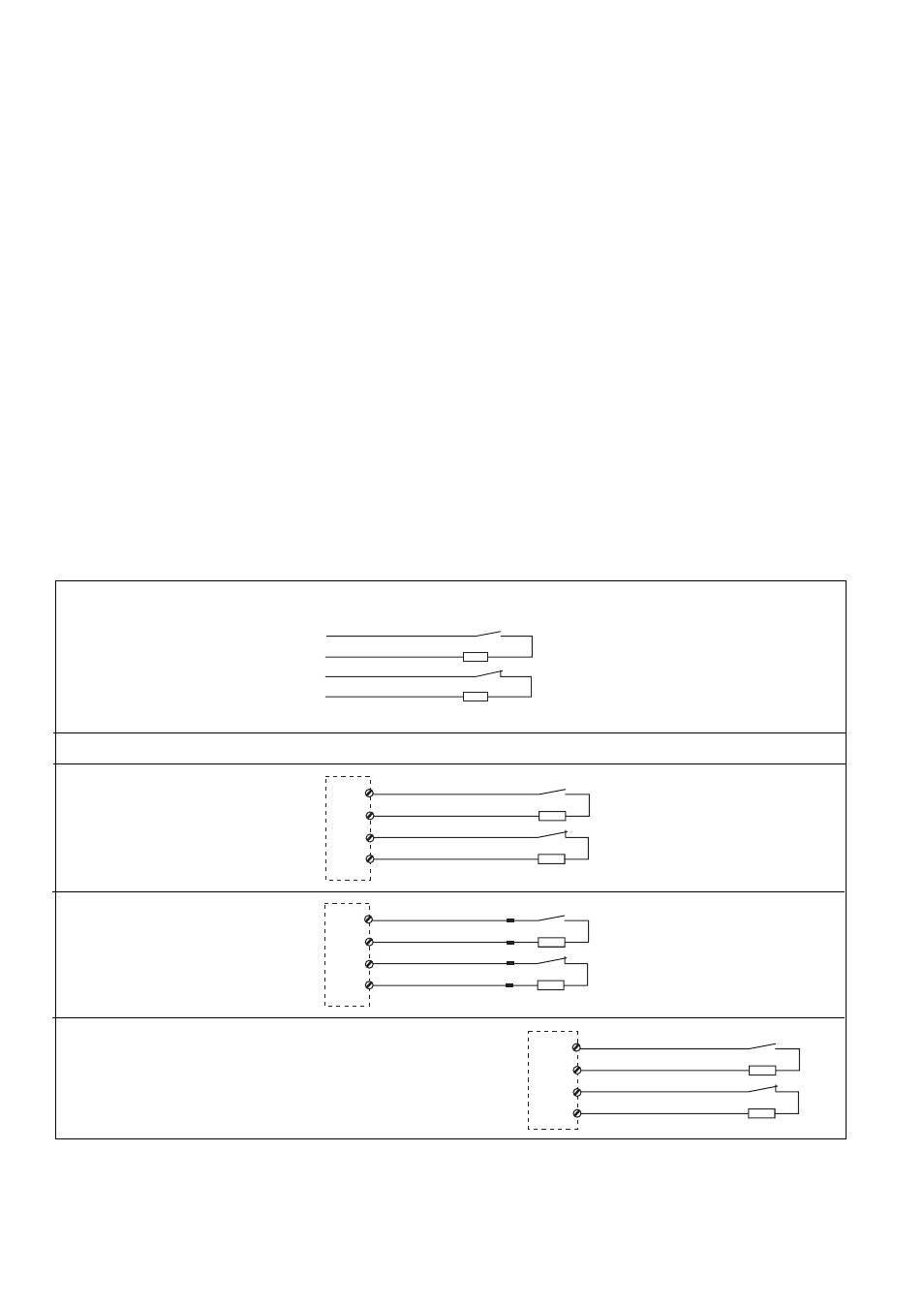
Der Sicherheitsschalter ist in unbetätigtem
Zustand dargestellt
The safety switch is shown in not operated
mode.
Le capteur de sécurité est représenté en
position non actionnée.
Belegung des
4-adrigen Kabels/Layout
of the 4-core cable/
Repérage du câble à 4
conducteurs
PSEN 2.1a-20/PSEN 2.1b-20
Anschluss an Auswertegerät
• PNOZ e3.1p
• PNOZ e3vp 10s
• PNOZ e3vp 300s
• Beispiel für
Sicherheits-
steuerung PSS
• Example of PSS
safety system
• Exemple pour
automate PSS
blau/blue/bleu
weiß/white/blanc
braun/brown/marron
schwarz/black/noir
S11
S12
S23
S24
O 16
O 17
blau/blue/bleu
weiß/white/blanc
braun/brown/marron
schwarz/black/noir
Taktausgang/Test pulse output/Sortie impulsionnelle
Eingang/Input/Entrée
I 00
I 01
Eingang/Input/Entrée
Taktausgang/Test pulse output/Sortie impulsionnelle
Connection to evaluation device
Raccordement à l'unité de contrôle
blau/blue/bleu
weiß/white/blanc
braun/brown/marron
schwarz/black/noir
• PNOZ e5.13p
1
2
3
4
blau/blue/bleu
weiß/white/blanc
braun/brown/marron
schwarz/black/noir
A1
S32
A1
S44
- PSEN 2.1a-20/8mm/5m /1switch PSEN 2.2-20 / 1 actuator PSEN 2.1-10 / 1 actuator PSEN 2.1b-20/PSEN 2.1-20 /8mm/10m/1unit PSEN 2.1a-20/PSEN 2.1-20/8mm /5m/1unit PSEN 1.2-20 / 1 actuator PSEN 1.1-20 / 1 actuator PSEN 1.1-10 / 1 actuator PNOZ m EF 2MM S1IM 230-240VAC IM 0.01-15 A S1IM 110-127VAC IM 0.01-15 A S1IM 24VDC IM 0.01-15 A UP S1IM 42-48VAC IM 0.01-15 A S1IM 24VAC IM 0.01-15 A S1IM 24VDC IM 0.01-15 A PNOZ 1 24VDC 3n/o 1n/c PNOZ 1 230-240VAC 3n/o 1n/c PNOZ 1 110-120VAC 3n/o 1n/c PNOZ 1 48VAC 3n/o 1n/c PNOZ 1 24VAC 3n/o 1n/c PSEN 2.1p-21/8mm/LED/1switch PSEN 2.1p-20/8mm/1switch PSEN 2.1p-21/PSEN 2.1-20 /8mm/LED/1unit PSEN 2.1p-20/PSEN 2.1-20 /8mm/1unit