Dvrt41direct vent gas fireplace, Framing and finishing, Final finishing – Vermont Casting DVRT41 User Manual
Page 7: Dvrt41 certified to, Gas inlet and manifold pressures, Gas specifications, High elevations, Gas line installation
7
DVRT41Direct Vent Gas Fireplace
10006740
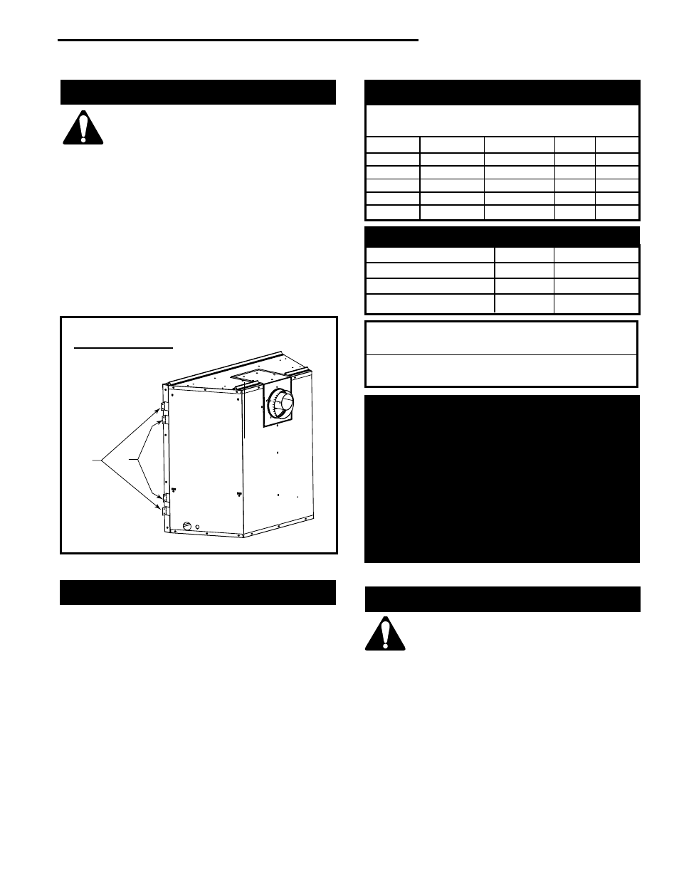
Framing And Finishing
Check fireplace to make sure it is lev-
elled and properly positioned.
To mount the appliance:
1. Choose the location.
2. This unit comes with four (4) flanges pre-mounted on
both sides of the fireplace to allow two different
drywall thicknesses to be used. Flange “A” is for 1/2”
drywall while flange “B” is for 5/8” drywall.
3. Bend the desired flanges out 90
°
on both sides of
the fireplace. Slide the fireplace into the framed
opening until the flanges contact the front surfaces
of the framing. Level the unit and secure it firmly in
place.
Final Finishing
Noncombustible materials such as brick or tile can be
extended over the edges of the face of the fireplace. Do
not cover the window frame assembly, any vent,
louvre assembly top or louvre assembly bottom. If a
Trim Kit is to be installed, brick and tile will have to be
installed flush with the side of this appliance.
DVRT41
Certified To
ANSI Z21.88-2002/CSA 2.33-2002
Vented Gas Fireplace Heater
Gas Inlet and Manifold Pressures
Natural
LP (Propane)
Minimum Inlet Pressure
5.5” w.c.
11.0” w.c.
Maximum Inlet Pressure
14.0” w.c.
14.0” w.c.
Manifold Pressure
3.5” w.c.
10.0” w.c.
Gas Specifications
MAX.
MIN.
GAS
INPUT
INPUT
MODEL
FUEL
CONTROL
B.T.U.H
B.T.U.H.
DVRT41RN
Natural Gas
Millivolt Hi/Lo
36,000
25,200
DVRT41RP
Propane
Millivolt Hi/Lo
36,000
27,000
DVRT41RFN
Natural Gas
Comfort Control
36,000
25,200
DVRT41RFP
Propane
Comfort Control
36,000
27,000
DVRT41EN
Natural Gas
24 Volt Hi/Lo
36,000
25,200
DVRT41EP
Propane
24 Volt Hi/Lo
36,000
27,000
High Elevations
Input ratings are shown in BTU per hour and are
certified without deration for elevations up to
4,500 feet (1,370m) above sea level.
For elevations above 4,500 feet (1,370m) in USA,
installations must be in accordance with the
current ANSI Z223.1/NFPA 54 and/or local codes
having jurisdiction.
In Canada, please consult provincial and/or local
authorities having jurisdiction for installations at
elevations above 4,500 feet (1,370m).
Gas Line Installation
When purging gas line the front glass
must be removed.
The gas pipeline can be brought in through the right
side of the appliance. Knockouts are provided at
convenient locations to allow for the gas pipe installa-
tion and testing of any gas connection.
The gas line connection can be made with properly
tinned 3/8" copper tubing, 1/2" rigid pipe or an approved
flex connector. Since some municipalities have
additional local codes, it is always best to consult your
local authority and the CSA-B149.1 installation codes.
For USA installations consult the current National Fuel
Gas Code, ANSI Z223.1/NFPA 54.
A
B
Fig. 5 Drywall flange location.
Flange Location for
Desired Drywall Depth
Flange
Drywall
Position
Depth
A
1/2” / 13mm
B
5/8” / 16mm
FP1539