Dvrt41 direct vent gas fireplace – Vermont Casting DVRT41 User Manual
Page 24
24
DVRT41 Direct Vent Gas Fireplace
10006740
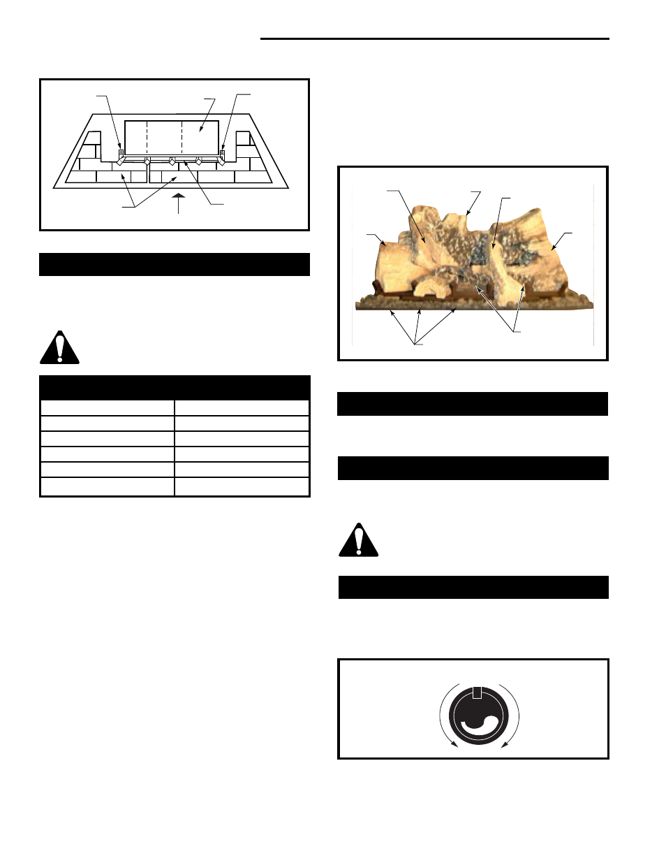
Installation of Logs
Remove front glass. (Refer to "Window Frame Assem-
bly Removal" Section, Fig. 46) Remove logs from
packaging.
As with all plastics — these are not toys
and should be kept away from children
and infants.
Refer to Figure 48.
1. Fit rear log (G7) in place. The two (2) underside
holes of the log fit over the two (2) pin studs of the
rear log bracket.
2. Place the front left log (G10). Position the front
branch between the second and third grates from
the left. The left end of this log with a slot will set
against the back of the first grate from the left.
3. Place the front right log (G6). Position the front
bottom recessed step of the log against the horizon-
tal bar of the front grate at the right. The center
bottom recessed step will set against the right end of
the burner housing.
4. Place burner lava rock and 1/3 of the bag of plati-
num embers on the front area of the burner. (Fig. 48)
5. Place the front center log (B129). Position the log
notch against the third grate from the right. The other
end of the log’s bottom has a round recessed hole
that rests on top of the round knob located at the
center of the rear log.
6. Position the cross over left top log (G8) by locating
the bottom rectangular slot of this log onto the rear
log knob on the left. The other end of the log will set
on top of the left front log cutout.
7. Place large lava rock around the front grate area as
shown in Figure 48.
Large Lava Rock
The large lava rock provided with this fireplace must be
placed on the firebox base around the sides of the
burner assembly and on the tray beneath the grate.
Under no circumstances should this
large lava rock be placed on any part of
the burner assembly.
Flame & Temperature Adjustment
For fireplaces equipped with Hi/Lo valves, flame adjust-
ment is accomplished by rotating the Hi/Lo adjustment
knob located near the centre of the gas control. (Fig. 49
or 50)
Burner Lava Rock Placement
Place burner lava rock on the burner in front of the front
logs. Do not place burner lava rock in the inside corners
of thefront logs.
Fig. 49 Flame adjustment knob for Honeywell valve.
LO
HI
Turn
counterclockwise
to decrease
flame height
Turn clockwise
to increase
flame height
Honeywell Valve
Grate
Burner
Hearth Panels
Front of Unit
FP1482
Fig. 47 Hearth panel location.
Screw
Screw
LOGS
DVRT41
Log Front Left
G10
Log Front Right
G6
Log Rear
G7
Log Crossover Left Top
G8
Log Front Center
G9
Log Identification Chart
Burner Lava Rock
and 1/3 of the bag
of Platinum
Embers
Volcanic Lava Rock
Log Front
Left
(F10)
Log Crossover
Left Top
(G8)
Log Rear
(G7)
Log Front Center
(G9)
Log
Front
Right
(G6)
LG339
Fig. 48 DVRT41 log, burner lava rock, platinum embers and
volcanic lava rock placement.