0 configuration, 1 configuration methods, 1 revolution configuration – Rice Lake IQ plus 2100SL Digital Bench Scale User Manual
Page 8: 2 edp command configuration, Revolution configuration, Edp command configuration
10
IQ plus 2100 Installation Manual
3.0
Configuration
To configure the IQ plus 210 indicator , the indicator
must be placed in setup mode. The setup switch is
accessed by removing the large fillister head scr w on
the enclosure backplate. Insert a scre wdriver into the
access hole and press the switch to enter setup mode.
When the indicator is placed in setup mode, the w ord
CONFIG
is shown on the display. The CONFIG menu is
the first of the main menus used to configure t
indicator. Detailed descriptions of these menus are
given in Section 3.2. When configuration is complete
press the setup switch ag ain to exit setup mode, then
replace the setup switch access screw.
3.1
Configuration Methods
The IQ plus 210 indicator can be configured by usin
the front panel b uttons to navigate through a series of
configuration menus or by sending commands or
configuration data to the EDP port. Configuration usin
the menus is described in Section 3.1.3.
Configuration using the EDP port can be accomplished
using either the EDP command set described in
Section 5.0 or Version 2.3 or later of the Re volution
™
configuration utilit .
3.1.1
Revolution Configuration
The Revolution configuration utility pr
vides the
preferred method for configuring the IQ plus 21
indicator. Revolution runs on a personal computer to set
configuration parameters for the indicator
. When
Revolution configuration is complete, configurati
data is downloaded to the indicator.
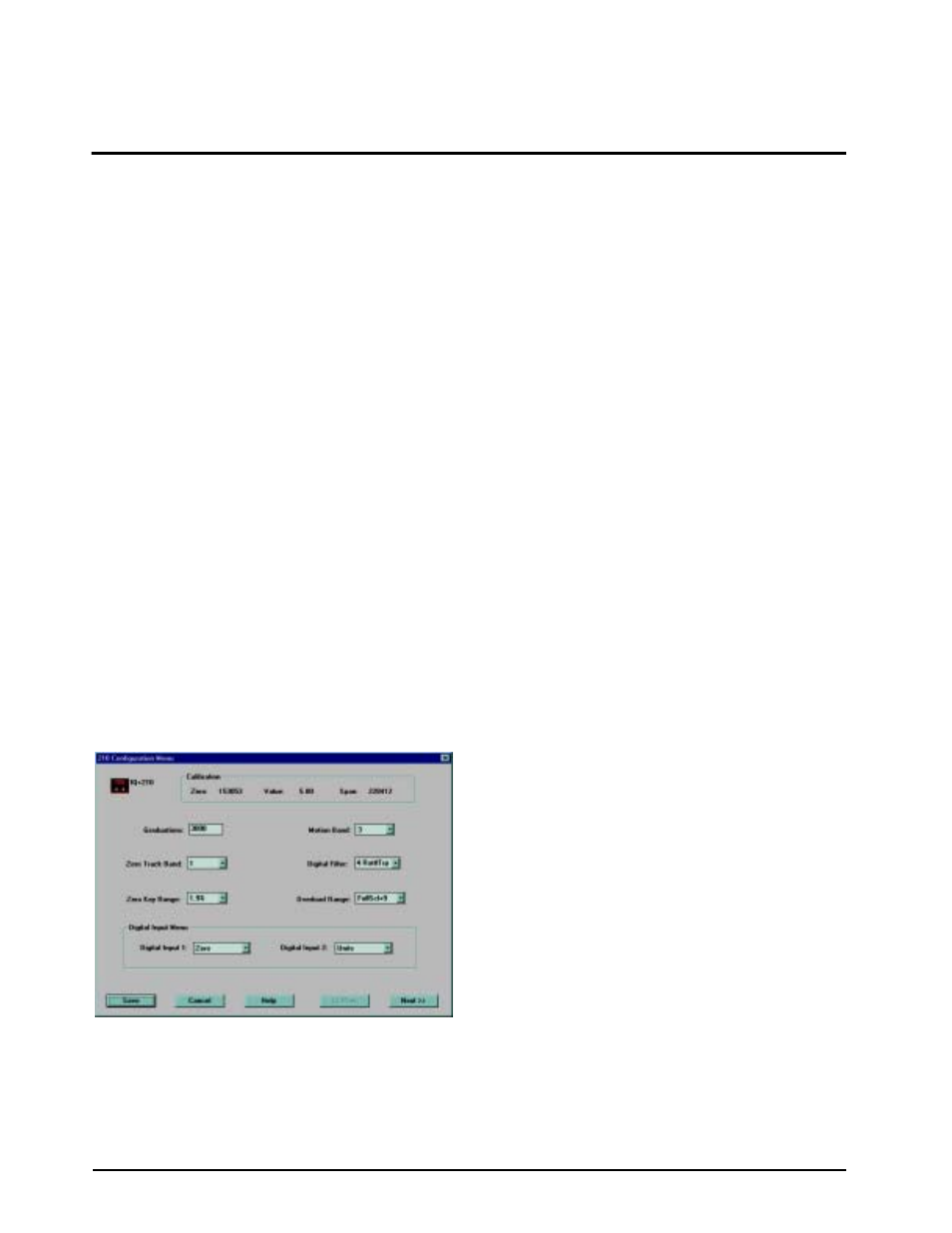
Figure 3-1. Sample Revolution Display
Revolution supports both uploading and do wnloading
of indicator configuration data. This capability allows
configuration data to be retrie ved from one indicator ,
edited, then downloaded to another.
To use Revolution, do the following:
1. Install Revolution on an IBM-compatible per-
sonal computer running Windows
®
3.11 or
Windows 95. Minimum system requirements
are 8MB of e xtended memory and at least
5MB of available hard disk space.
2. With both indicator and PC po
wered off,
connect the PC serial port to the RS-232 pins
on the indicator EDP port.
3. Power up the PC and the indicator . Use the
setup switch to place the indicator in setup
mode.
4. Start the Revolution program.
Figure 3-1 shows an example of one of the Re volution
configuration displays
Revolution provides online help for each of its
configuration displays. Parameter descriptions provided
in this manual for front panel configuration can also b
used when configuring the indicator using R volution:
the interface is different, but the parameters set are the
same.
3.1.2
EDP Command Configuration
The EDP command set can be used to configure the I
plus 210 indicator using a personal computer, terminal,
or remote keyboard. Like Revolution, EDP command
configuration sends commands to the indicator serial
port; unlike Revolution, EDP commands can be sent
using any external device capable of sending ASCII
characters over a serial connection.
EDP commands duplicate the functions available using
the indicator front panel and pro vide some functions
not otherwise available. EDP commands can be used to
simulate pressing front panel b uttons, to configure th
indicator, or to dump lists of parameter settings. See
Section 5.0 on page 22 for more information about
using the EDP command set.