2 bench scale adjustments, 3 clamshell installation, Bench scale adjustments – Rice Lake IQ plus 2100SL Digital Bench Scale User Manual
Page 31: Clamshell installation
27
6.6.2
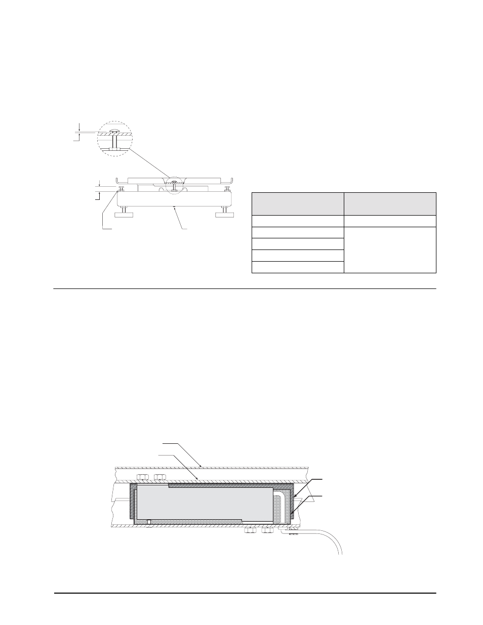
Bench Scale Adjustments
The RL2100 bench scale uses a number of scre ws to
provide overload and underload protection for the load
cell. These protection screws are all set at the f actory
before shipment; use the follo wing information to
verify and reset protection screws.
Figure 6-10. RL2100 Protection Screw Adjustments
•
Lift-up Protection Screws
Set lift-up protection screw height to 0.06 in (1.52
mm).
•
Overload Protection Set Screw
Elevate the scale base to allow sufficient clearance
to adjust the set scre w, then center a load equal to
125% of scale capacity on the platter . Use a he x
wrench to advance the set screw until it touches the
load cell, then back of f 1/6 of a turn. Verify
calibration, then add a drop of non-permanent
thread adhesive (such as
LOCTITE
®
) to prevent the
set screw from vibrating loose.
•
Corner Overload Protection Screws
The correct height of the corner o
verload
protection screws depends on the scale capacity .
Adjust the four scre ws to the heights sho wn in
6.6.3
Clamshell Installation
Protective stainless steel clamshells are a vailable as an
option for all RL2100 bench scales. Clamshells are
pre-drilled for load cell scre ws, overload screw, and
cables. Existing load cell shims are reinstalled inside
the clamshells.
To install the clamshell, do the following:
1. Remove platter, spider plate, and load cell
using the procedure described in Section 6.6.1
2. Install lower clamshell in base. Route load cell
cable through lower clamshell and grommet.,
then reinstall lower shim and load cell so that
no part of the load cell touches the clamshell
enclosure. Replace lower load cell screws and
lockwashers. Torque to 80 in-lb (9.0 N-m).
3. Install upper clamshell, ensuring clearance on
all sides to pre vent binding against the lower
clamshell. Reinstall upper shim, spider plate,
lockwashers, and upper load cell scre
ws.
Torque screws to 80 in-lb (9.0 N-m).
4. Replace scale platter. Ensure that scale is level.
5. Readjust lift-up protection screws and overload
protection set screw on bottom of scale base as
described under Section 6.6.2.
6. Connect load cell cable to indicator . Power-up
indicator and recalibrate scale.
Figure 6-11. Clamshell Installation
0.06 in
D
Corner overload
protection screws (4)
Lift-up protection screws (2)
Overload protection
set screw
Model (Capacity)
Corner Overload Protection
Screw Height (D)
5 lb (2.5 Kg)
0.56 in (142 mm)
10 lb (5 Kg)
0.50 in (127 mm)
25 lb (10 Kg)
50 lb (25 Kg)
100 lb (50 Kg)
Table 6-4. Corner Protection Screw Height
Upper Clamshell
Lower Clamshell
Spider Plate
Platter
Load Cell