8 serial ports, 1 com1 (port1) db9 connector, 2 com2 pin header connector – Kontron KT965 Series User Manual
Page 38: Kt965 family, Serial ports
KT965 Family
KTD-00699-S
Public User Manual
Date: 2010-04-15 Page
38 of 90
4.8
Serial Ports
Two RS232 serial ports are available on the KT965 boards
The typical interpretation of the signals in the COM ports is as follows:
Signal
Description
TxD
Transmitte Data, sends serial data to the communication link. The signal is set to a marking
state on hardware reset when the transmitter is empty or when loop mode operation is
initiated.
RxD
Receive Data, receives serial data from the communication link.
DTR
Data Terminal Ready, indicates to the modem or data set that the on-board UART is ready to
establish a communication link.
DSR
Data Set Ready, indicates that the modem or data set is ready to establish a communication
link.
RTS
Request To Send, indicates to the modem or data set that the on-board UART is ready to
exchange data.
CTS
Clear To Send, indicates that the modem or data set is ready to exchange data.
DCD
Data Carrier Detect, indicates that the modem or data set has detected the data carrier.
RI
Ring Indicator, indicates that the modem has received a telephone-ringing signal.
The connector pinout for each operation mode is defined in the following sections.
4.8.1 Com1 (Port1) DB9 Connector.
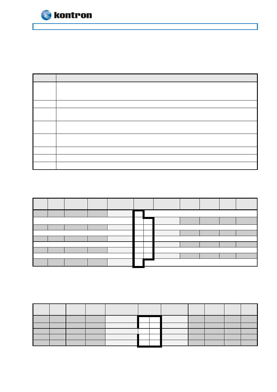
4.8.2 Com2 Pin Header Connector.
The pinout of Serial ports Com2 is as follows:
Note
Pull
U/D
Ioh/Iol
Type
Signal
PIN
Signal
Type
Ioh/Iol
Pull
U/D
Note
-
I
DCD 1
2
DSR
I
-
-
I
RxD 3
4
RTS
O
-
-
O
TxD 5
6
CTS
I
-
-
O
DTR 7
8 RI
I
-
-
-
PWR
GND 9
10
5V
PWR
-
-
1
Note 1:
The Com2 header 5V supply is fused with a 1.1A resetable fuse.
If the DB9 adapter (ribbon cable) is used, the DB9 pinout will be identical to the pinout of Serial Com1
Note
Pull
U/D
Ioh/Iol
Type
Signal
PIN
Signal
Type
Ioh/Iol
Pull
U/D
Note
-
-
PWR
GND 5
9 RI
I
-
/5K
-
O
DTR 4
8
CTS
I
-
/5K
-
O
TxD 3
7
RTS
O
-
/5K
-
I
RxD 2
6
DSR
I
-
/5K
/5K
-
I
DCD 1