ETS-Lindgren 2115 Multi-Axis Positioning Systems (MAPS) User Manual
Page 22
22
|
Installation
9. When all anchor plates are securely mounted, remove the 1/4–20 screws that hold
the anchor plates to the base. Discard the screws.
10. Use a bubble level to verify the turntable unit is flat. This is a preliminary check only;
final leveling of the turntable will be completed in a later step.
11. Use shim plates to level the table. The shim plates will remain in place after the
installation.
U
PPER
D
RIVE
U
NIT
R
EMOVAL
When installing the MAPS in an existing chamber, it may be necessary to
remove the upper drive unit to avoid damage to the chamber or to the MAPS.
Following are the steps to separate the upper and lower drive units. See
assembly drawings 111040, 109987, and 110073 located in the back pocket of
the manual for details.
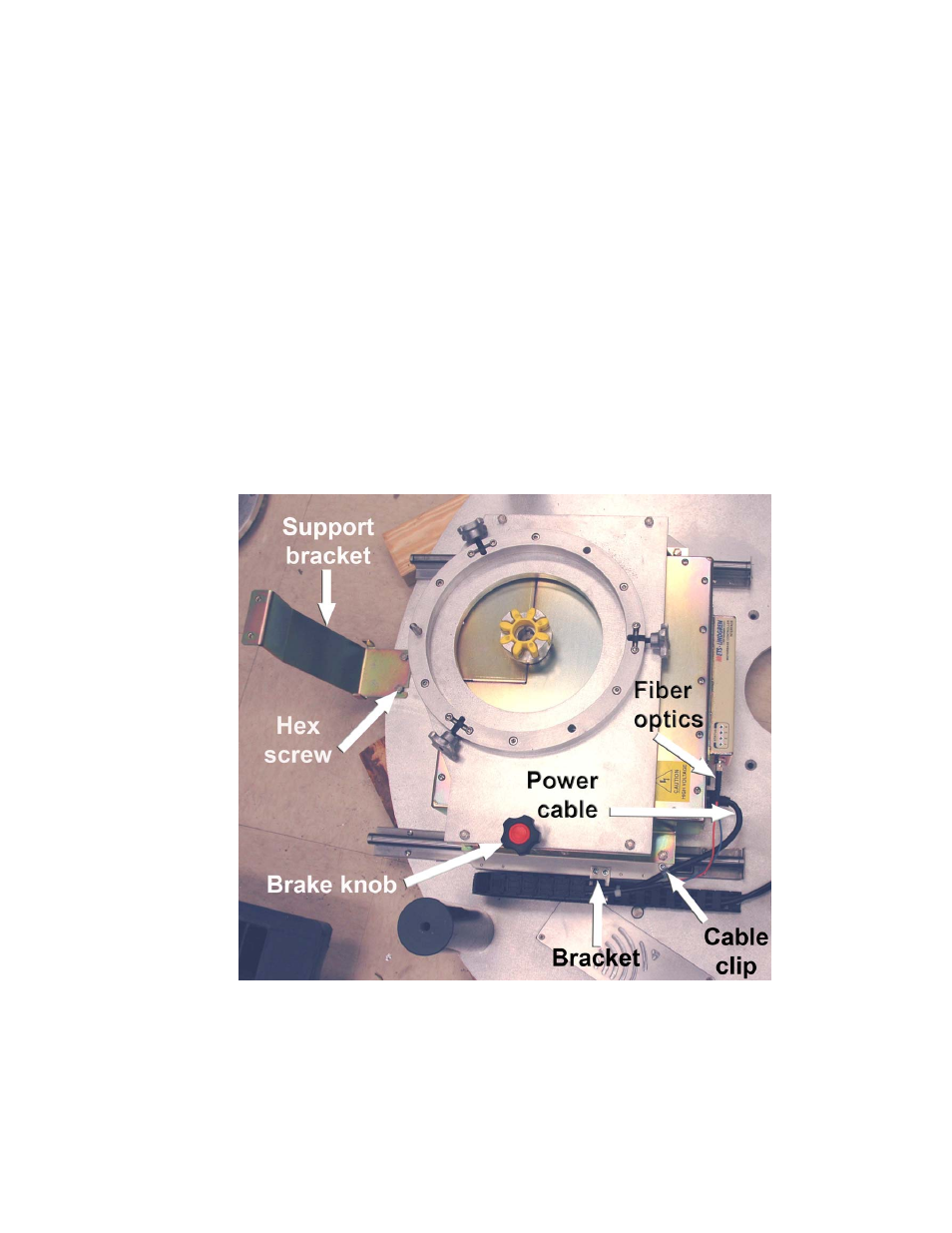
12. Prior to disconnecting the fiber optic cables from the upper drive unit, label and mark
the locations for reconnection.
13. Verify the fiber optic cables to the upper motor base are not switched.
- SMART 200 Reverb Chambers (45 pages)
- 6402 Helmholtz Coil (24 pages)
- 3625-2 LISN (15 pages)
- 3701 Line Probe (15 pages)
- 3725-2M LISN (19 pages)
- 3810-2 LISN (25 pages)
- 3816-2 LISN (21 pages)
- 3850-2 LISN (19 pages)
- 4825-2 LISN (25 pages)
- 1052 Antenna Tower Positioner (23 pages)
- 2005 Single Axis Positioner (32 pages)
- 2090 Controller (178 pages)
- 2110 Multi-Axis Positioning Systems (MAPS) (48 pages)
- 2165 Turntable (46 pages)
- 2171B Boresight Antenna Tower (64 pages)
- 2175 Antenna Tower (41 pages)
- 2181 Turntable (44 pages)
- 2187 Turntable (36 pages)
- 2188 Turntable (39 pages)
- 7-TR Tripod Positioner (49 pages)
- 7000-001 EMCenter Modular RF Platform (41 pages)
- 7405 E & H Near Field Probe Set (51 pages)
- 91197-1 Current Probe (57 pages)
- 95236-1 Current Probe (27 pages)
- HI-1501 Microwave Oven Survey Meter (28 pages)
- HI-1600 Microwave Oven Survey Meter (26 pages)
- HI-1710A Microwave Oven Survey Meter (57 pages)
- HI-1801 Microwave Oven Survey Meter (24 pages)
- HI-2200 RF Survey Meter (53 pages)
- HI-2602 Interlock Monitor (22 pages)
- HI-2790B Calibration Comparison System (44 pages)
- HI-3603 VLF Survey Meter (55 pages)
- HI-3604 ELF Survey Meter (44 pages)
- HI-3624(A) Survey Meter (22 pages)
- HI-3627 ELF Magnetic Field Meter (36 pages)
- HI-3637 VLF Magnetic Field Meter (48 pages)
- HI-3638 ELV/VLF Electric Field Meter (41 pages)
- HI-3702 Induced Current Meter (34 pages)
- HI-3804 RF Industrial Compliance Meter (25 pages)
- HI-4416 Numeric EMF Readout Unit (38 pages)
- HI-4433-CH Magnetic Field Probe (42 pages)
- HI-6005 Electric Field Probe (152 pages)
- HI-6100 Field Monitor (71 pages)
- HI-6113 Laser Data Interface and Probe Measurement System (49 pages)