Elecraft KAT3 User Manual
Page 7
7
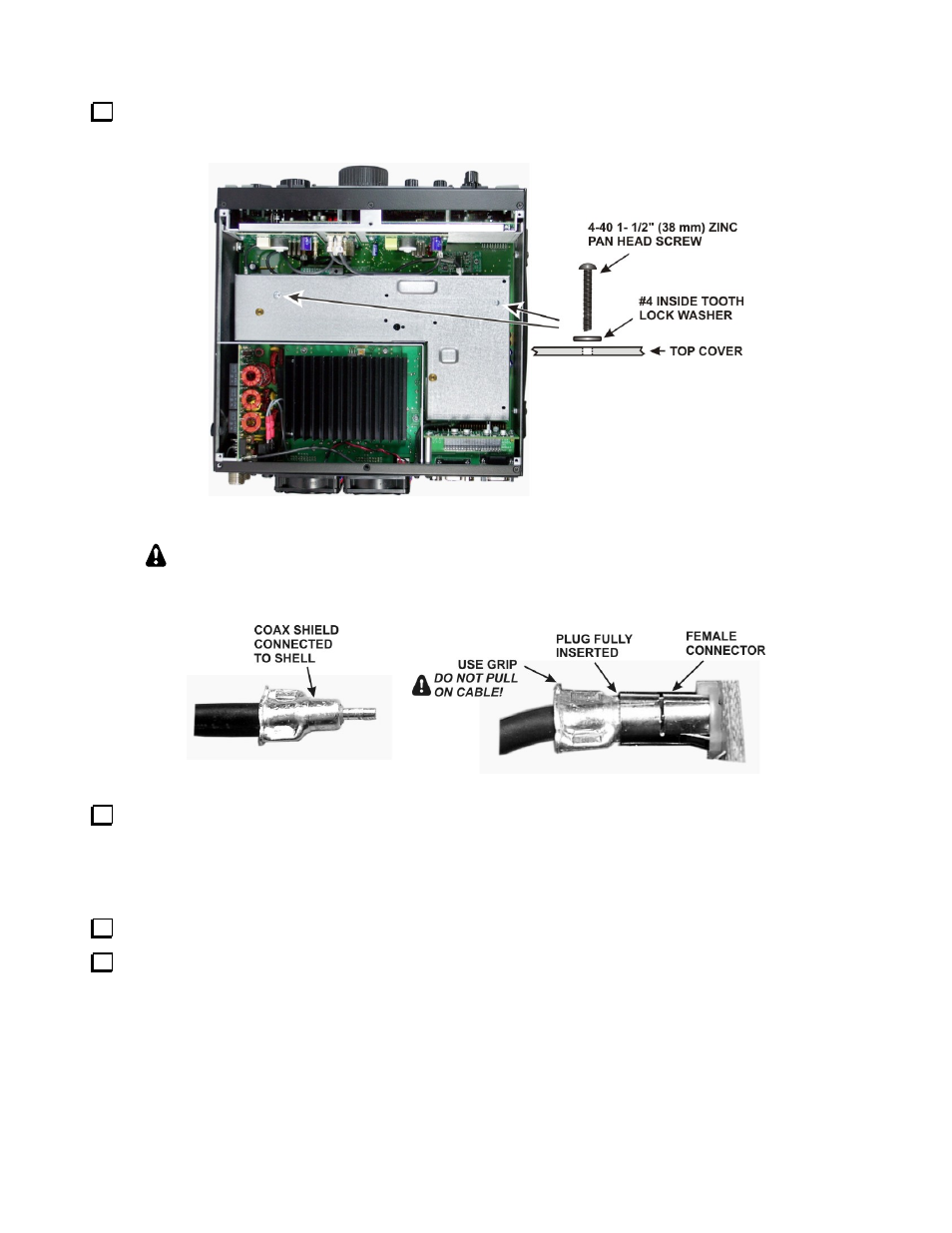
Remove the two 1-1/2” (38 mm) screws and lock washers shown in Figure 2. These screws extend all the
way through the KRX3 module and secure it to standoffs mounted on the main RF board that fills the bottom of
the K3.
Figure 2. Removing the KRX3 Module.
In the following steps you will handle small TMP coaxial connectors. These are friction-
fit connectors shown in Figure 3. Handle the connectors by the grips as shown. Do not pull
on the coaxial cable.
Figure 3. TMP Cable Connectors.
Hold the KRX3 module by the two brass knurled nuts on the top, and lift it straight up to gain access to the
small TMP coaxial connectors plugged into the module. There are two along the front. There may be one at the
back as well, depending upon the options installed. As you lift the KRX3 module, it will unplug from two small
interface circuit boards. One is at the front and the other is at the rear. These small boards may come out with
the module or they may remain attached to the K3 main RF board.
Unplug the TMP coaxial cables leading to the KRX3 module, then lift the module free and set it aside.
Locate the two small interface circuit boards, remove them and put them in a safe place.