Installation procedure – Elecraft KAT3 User Manual
Page 6
6
Installation Procedure
Removing the Top Cover
Disconnect power and all cables from your K3.
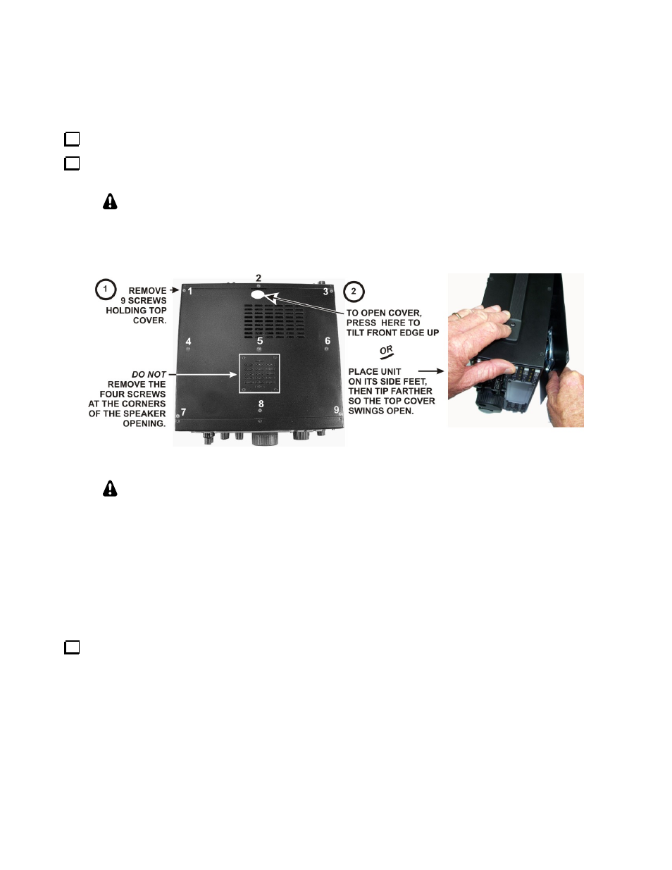
Remove the nine screws to free the top cover as shown in Figure 1. After the cover is open, lift it gently to
reach the speaker wire connector. Unplug the speaker then set the top cover aside in a safe place.
Whenever you remove screws from a panel, if one screw seems too tight to loosen
without damaging it, first loosen the other screws then try again. Sometimes one screw
binds in its hole when the other screws are tightened.
Figure 1. Removing K3 Top Cover.
CAUTION:
Touch an unpainted metal ground or wear a grounded wrist strap
before touching components or circuit boards inside the K3. See Preventing ESD Damage on
page 4 for more information.
Removing the KRX3 Subreceiver Module
If your K3 is equipped with the optional KRX3 Subreceiver, you must remove the subreceiver module to install
the KAT3. The KRX3 subreceiver module is the “L” shaped metal enclosure (see Figure 2). Remove the
subreceiver module as follows:
Remove the chassis stiffener bar that runs across the top of the K3 chassis and is attached to the side panels.
If the KPA3 is installed, the stiffener will be attached to the KPA3 shield by two screws. These screws may have
nuts and lock washers or they may thread into permanently-attached PEM nuts on the stiffener bar.