Reinstalling the krx3 subreceiver module – Elecraft KAT3 User Manual
Page 11
11
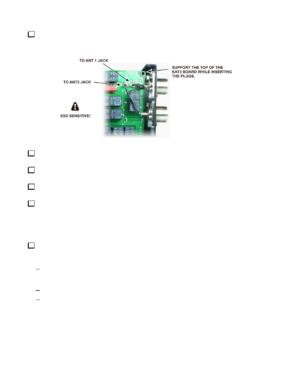
Plug the connectors on the wires leading to the ANT1 and ANT2 jacks into the KAT3 board as shown in
Figure 10. ANT1 goes to the connector nearest the rear panel, and ANT2 goes to the one farthest from the rear
panel as shown. Support the top of the KAT3 board when plugging in these connectors. The fit may be very
tight and the KAT3 board does not have any mechanical support at the top yet.
Figure 10. Installing the KAT3 Board.
Replace the right side panel on the K3, installing the screws shown in Figure 6 first. Use the 4-40 3/16”
(4.8 mm) screws you removed earlier.
Replace the 4-40 1/4” (6.4 mm) zinc pan head screw and washer that holds the KAT3 board to the standoff
as shown in Figure 5.
Replace the 4-40, 3/16” (4.8 mm) black flat head screw that secures the back panel to the 2D fastener as
shown in Figure 5.
Replace the two 4-40 3/8” (9.6 mm) black flat head screws, lock washers and nuts to secure the heat sinks
of U13 and U12 to the side panel as shown in Figure 4.
Reinstalling the KRX3 Subreceiver Module
If your K3 does not have a KRX3 subreceiver, go directly to Replacing the Top Cover on page 12.
If your K3 is equipped with the KRX3 Subreceiver, turn to your KRX3 Subreceiver Installation and
Operation manual, Installing the KRX3 Subreceiver Module section to replace the KRX3 module. Be especially
careful to do the following as described in that procedure:
Be sure the cover on battery BT1 on the K3 RF board is in place. The cover is essential to avoid
shorting the battery. The outer rim of the battery is the positive terminal, and may come in contact with
the grounded bottom of the KRX3 enclosure if the cover is not in place.
Be sure all the TMP cables are properly connected or your K3 will not operate properly.
Be sure the TMP cable to J85 on the subreceiver module is routed as shown to prevent signal leakage
between the KRX3 and the K3 main receiver.