Installing the ant2 connector, Installing the kat3 module – Elecraft KAT3 User Manual
Page 10
10
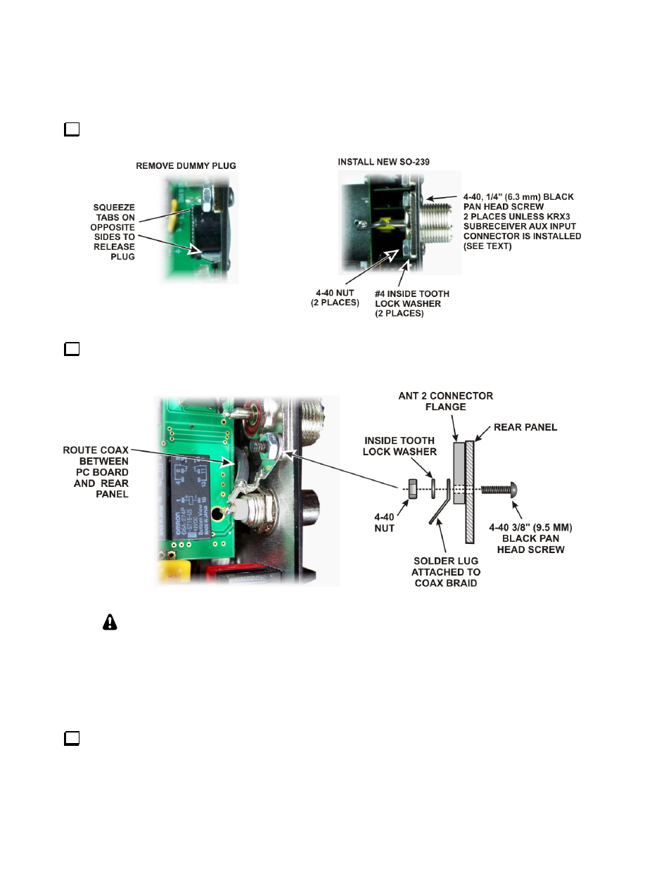
Installing the ANT2 Connector
Remove the dummy plug from the ANT2 connector hole in the back panel. The plug is released by
squeezing two tabs on opposite sides (see Figure 8).
Figure 8. Installing ANT2 Connector.
Install the SO239 coaxial connector in the ANT2 space using the hardware shown in Figure 8.If the KRX3
AUX RF connector is installed, remove the 3/8” (9.5 mm) black pan head screw and associated hardware from
the lower hole, then use the same screw to replace the AUX RF ground lug as shown in Figure 9
Figure 9. Installing AUX RF Ground Lug.
As you install components and reassemble your K3, be sure all the screws are in place
and secure, but do not over tighten them. Failure to tighten all screws may result in poor
shielding of sensitive components, resulting in possible noise or birdies in the receiver as well
as other difficult-to-trace problems.
Installing the KAT3 Module
Plug the KAT3 board into P70 on the RF board. This is the same plug that was used by the KANT3. Wear
a wrist strap or touch an unpainted metal ground before handling the boards. Flex the back panel slightly
as needed for the board to clear the lip at the top, just as you did when removing the KANT3 board. If the AUX
RF connector is installed, route the coaxial cable between the KAT3 board and rear panel as shown in Figure 9.