Elecraft KPA100UPKT User Manual
Page 8
8
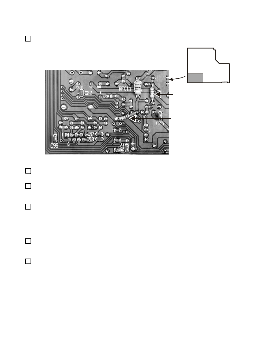
Turn the PCB over the and locate the area on the bottom shown in Figure 8.
R33 - 1K
(If Not Installed Elsewhere
See Text)
R40 - 22K with
Insulated Lead
Bottom Side
of Board
Figure 8. Installing R33 and R40.
St
r
i
p
1/
4”
(
3mm)
of
i
ns
ul
at
i
on
of
f
of
t
he
#20
i
ns
ul
a
t
e
d
wi
r
e
,
a
nd
pl
a
c
e
t
he
i
ns
ul
a
t
i
on
ove
r
one
l
e
a
d
of
22k
(
r
e
d-red-org)
1/4W resistor R40.
Trim and bend the leads of R40 to just reach the two solder pads shown in Figure 8, with the insulated sleeve protecting
against shorts to the adjacent solder pads. Solder R40 in place as shown, taking care not to cause a solder bridge to the nearby
solder pads.
Check the PCB on both top and bottom to see if R33 has been previously installed. It may be mounted on top of the
board across the leads of RFC3. If R33 is not already installed, position 1k (brn-blk-red) 1/4W resistor R33 as shown and
solder it in place.
Part IV: Other Changes
On the top of the PCB, locate resistor R4 next to crystal X1 and near the edge where the speaker leads are connected.
Check the value of R4. It should be 100k (brn-blk-yel). If it is any value other than 100k, replace it with the 100k (brn-blk-
yel) 1/4W resistor provided.
Check the hex jack screws on AUX I/O connector J8 on the back panel. If the threaded sections do not reach all the way
through the mounting flanges on J8, replace them with the jack screws provided.