Elecraft KPA100UPKT User Manual
Page 6
6
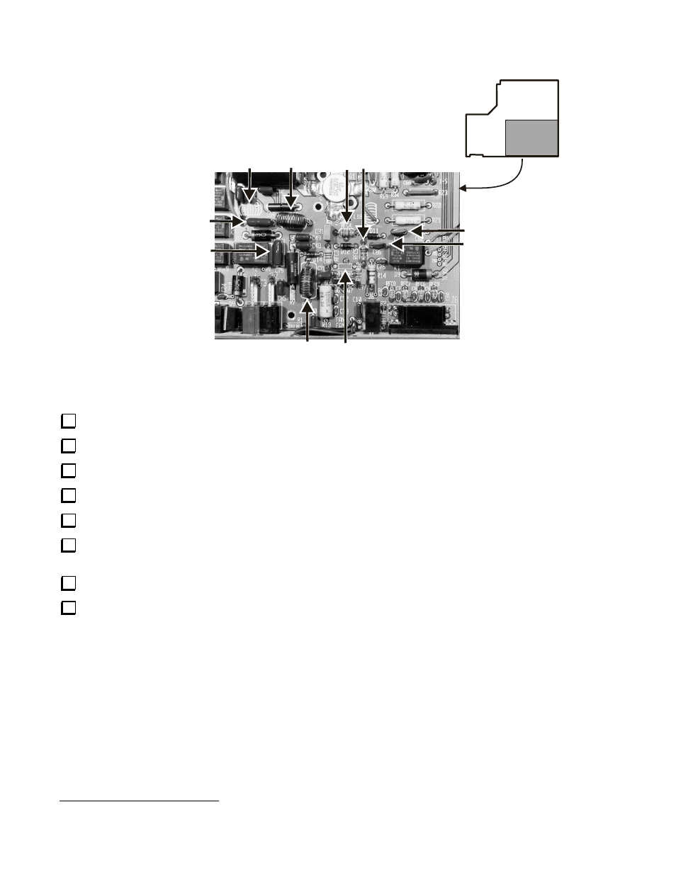
C67 - .0047 µF 100V
C64 - .0047 µF 250V
C79 - .0047 µF 250V
RFC4 & RFC5
15 µH
L16
37T T50-1
RFC1
37T T50-1
R12
Removed
L15
Removed
NOTE - If you have a Rev A PCB:
1) L15 has no reference designator
shown on the board.
2) L16 is labeled RFC2.
C86 - .0047 µF 100V
Figure 5. T/R Switch Components.
Replace RFC4 with a 15 µH (brn-grn-blk) RFC.
Replace RFC5 with a 15 µH (brn-grn-blk) RFC .
Remove toroid L15. Nothing replaces it.
Remove capacitor C16 and clear the holes of solder. A new part will be installed here later.
Remove toroid L16 and clear the holes of solder. A new toroid will be installed here later.
Replace C79 with a .0047 µF (472) 250V or greater voltage capacitor,
LS
0.
4”
. The capacitor supplied may be a
different style than that shown in Figure 5.
Remove RFC1 and clear the holes of solder. A new RFC will be installed later.
Prepare a new L16 and RFC1
1
:
1.
Use T50-1 cores: blue, 0.5" (12.7 mm).
2.
Cut 27" (69 cm) lengths of #26 red enamel wire for each inductor.
3.
Wind 37 turns on each core as shown in Figure 6.
1
Pre-wound toroids are available from an Elecraft-approved source; see Pre-Wound Toroids, page 2