Elecraft KPA100UPKT User Manual
Page 3
3
Lift the KPA100 up slightly to access the cable connections along the right side. Unplug the ribbon connector that
attaches to the control board, the speaker, Aux 12V, and Aux RF connectors that attach to the K2 RF board. Lift the KPA100
off of the K2 and set it top down on a clean surface to avoid scratching the heat sink. Set the K2 aside in a safe place.
Remove the seven screws attaching the shield to the hex standoffs, lift the shield off and set it aside.
If you have the shield modification kit installed, remove the corner screw at J2 holding the solder lugs that connect the
shell of J2 to the hex standoff and shield.
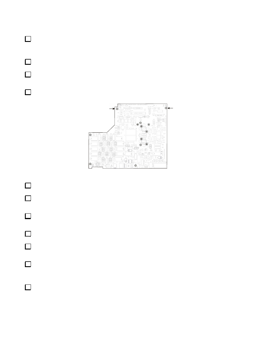
Remove the seven hex standoffs and lock washers that secure the board to the heat sink. Two of the standoffs are near
the center of the board (see Figure 1). Do not lose the lock washers.
1/2 inch
Standoff
1/2 inch
Standoff
Q3
Q4
Q2
Q1
Figure 1. Removing the KPA100 PCB.
Remove the three screws that attach the KPA100 back panel to the heat sink.
De-solder the two speaker leads at the loudspeaker. Take care not to drop solder on the speaker cone or otherwise
damage it.
Remove the screws securing Q3 and Q4. These screws secure the transistors to the heat sink. Do not lose the lock
washers.
Remove the four screws that secure PA power transistors Q1 and Q2 to the heat sink. Do not lose the lock washers.
Gently lift the KPA100 PCB off of the heat sink. Set the heat sink aside in a safe, clean place. Take care not to damage
the two thermal pads for the transistors. These are small rectangular pads that should remain attached to the heat sink.
Carefully peel the thermal pads off of PA power transistors Q1 and Q2 so that the bottom of each transistor shows clean
metal. You have new thermal pads in the kit to use when reassembling the KPA100. However, the old pads can be reused if
you remove them without tearing or otherwise damaging them.
Remove capacitor C83 from the PCB. Do not damage it. C83 is a large 1000 pF silver mica mounted on the PCB near
the end of binocular core transformer T2. C83 is soldered to the board with two short leads that rest on top of the solder pads
at the end of T2. The leads do not pass through the board. You can remove it easily by removing any excess solder on the
pads, then heating one lead at a time while gently lifting that end of the capacitor. Yo
u’
l
l
i
ns
t
a
l
l
i
t
di
r
ec
t
l
y
on
t
he
e
nd
of
T2
later.