Pre-wound toroids, Parts list, Part i: removing the kpa100 board – Elecraft KPA100UPKT User Manual
Page 2
2
Limit soldering iron contact to a few seconds at a time.
Use a large vacuum desoldering tool (solder sucker) such as described under Tools Required above. Solder wick is
useful for removing excess solder from a joint, but requires great care if you use it to clean out a hole.
Invest in a PC board vice with a heavy base if possible. This makes parts removal easier because it frees up both hands.
If in doubt about a particular repair, ask for advice from Elecraft or from someone else with PCB repair experience.
Pre-Wound Toroids
Two new toroids are required for this upgrade. They are not difficult to wind, and full instructions are provided. If you prefer
not to wind them yourself, you can obtain a pre-wound toroids from an Elecraft-qualified source. Ordering information can
be found on our web site, www.elecraft.com. You do not need to send your cores or wire to the winding service.
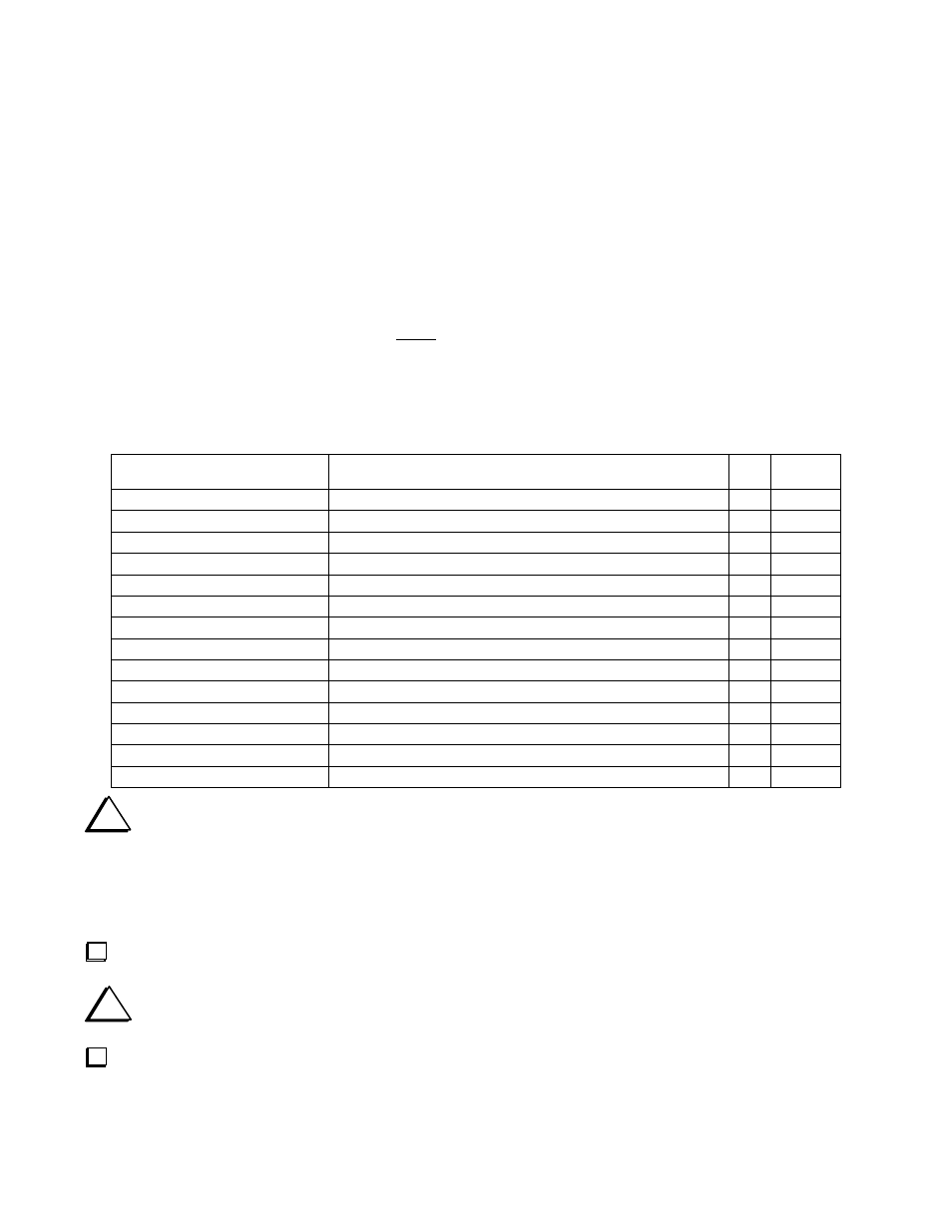
Parts List
We recommend that you do a complete inventory before beginning assembly. The inventory helps you correctly identify all
the parts to avoid mistakes during assembly. The numbers or colors shown in parenthesis are those you should find on each
part. There may be other letters and numbers stamped on the parts as well.
Reference. Designator
Description
Qty
Part
Number
C64, C79
Capacitor, .0047 µF 5% 250V or greater, LS 0.4
2
E530262
C67, C86
Capacitor, 0047 µF, 100V, LS 0.2
2
E530102
L16, RFC1
Toroid Core, T50-1 (blue)
2
E680001
R4
Resistor, 100k (brn-blk-yel) 1/2W
1
E500006
R19, R20
Resistor, 1.6
ohm
(
1.
6
Ω)
2W
2
E500130
R22
Resi
st
or
,
300
ohms
(
300Ω)
2W
1
E500129
R33
Resistor, 1K (brn-blk-red) 1/2W
1
E500013
R38, R39
Resi
st
or
,
22
ohm
(
22
Ω)
3
W
2
E500128
R40
Resistor, 22k (red-red-org)
1
E500090
RFC4, RFC5
RF Choke, 15 µH (brn-grn-blk)
2
E690006
Misc.
#26 Red Enamel Wire
6ft
E760002
Misc.
#20 Solid Black Insulated Wire
5in
E760006
Misc.
Thermal pad (for Q1 and Q2)
2
E980051
Misc.
Jack screw, Hex, 4-40, M/F
2
E700078
i
The following procedures require you to remove components from the KPA100 printed-circuit board (PCB).
We strongly recommend you use the tools listed under Tools Required and follow the procedures carefully to avoid
damage to the PCB. See the hints under Soldering and Desoldering.
Part I: Removing the KPA100 Board
Disconnect all wires connecting your K2/100 to external devices.
i
Set aside in a safe place all hardware you remove in the following steps for reinstallation later.
Remove the six screws that attach the KPA100 to the K2: there are two at the top front corners, one on each side of the
K2, and two at the rear.