Very important – Elecraft KPA100UPKT User Manual
Page 10
10
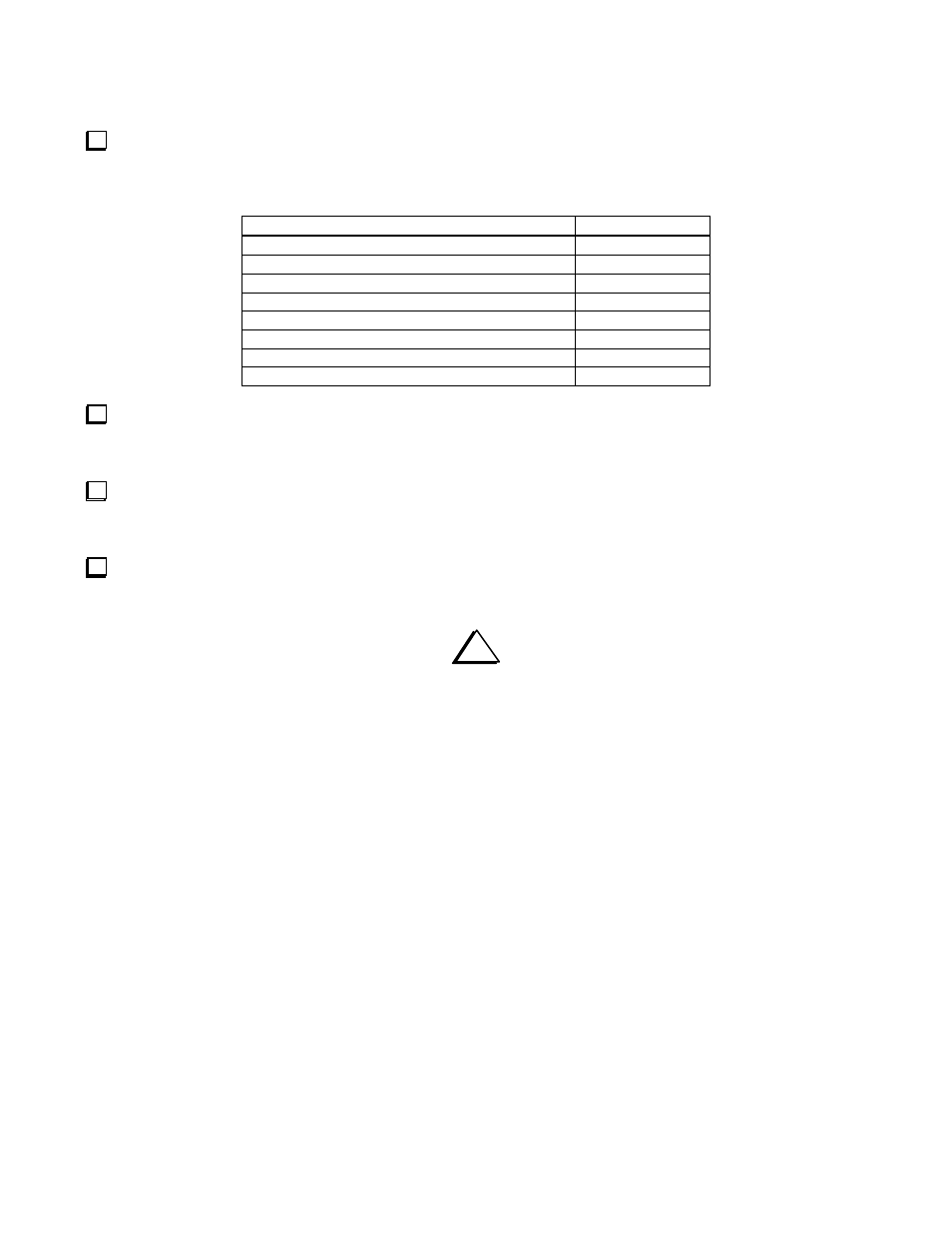
Make the resistance measurements listed below, touching the DMM (+) lead to the indicated points, and the (-) lead to
ground. Note: The reading from J3 to ground may initially read a short (0 ohms) because of the large electrolytic capacitor on
the 12 V line. Use a low resistance range, and wait up to 20 seconds for the reading to stabilize.
KPA100 Test Points (+)
Resistance
J3 + lead (red) (see note above)
> 5 k
Q1 collector
> 10 k
Q2 collector
> 10 k
Q1 base
11-16 ohms
Q2 base
11-16 ohms
J2 (antenna jack) center pin
> 10 k
Q9 tab (near rear panel)
> 10 k
D13 cathode (banded end)
> 10 k
Realignment of the KPA100 should not be necessary after making these modifications. If you wish to test or realign the
modified KPA100 before replacing it in your K2, do so now by setting it on books or other support next to the K2 as
described in the KPA100 manual.
Replace the ground lugs, screw and nut removed earlier from one corner of the ANT connector. If your KPA100 does
not have ground lugs attaching the corner of the shield to the ANT connector and the spring clips that ground the shield to the
sides of the K2 case and KPA100 back cover, you must upgrade the shield. Order KPA100SHDKT from Elecraft.
Install the shield on the standoffs with the seven screws you removed earlier, and replace the KPA100 in your K2 by
reversing the steps on page 2.
i
VERY IMPORTANT!
Remember to tighten the mounting screws on Q1 and Q2 after
10 to 12 hours of operation. Failure to do so could destroy the transistors.
Schematic Diagrams
Updated schematic diagrams including the modifications you just made are shown on the following pages.