Elecraft KAT1 Manual User Manual
Page 5
5
Cut L1's leads to about 1/2" (12 mm) long. Completely remove the enamel insulation from the leads
to within 1/8” (3 mm) of the core. The enamel wire provided can be heat-stripped using a small amount of
solder on the tip of your iron. Stripping using this method takes 4-6 seconds.
Install L1 vertically on the PC board as shown by its component outline, then pull the leads taut on
the bottom of the board.
Trim and solder the leads of L1. When soldering, make sure that the solder binds well to the leads. If
the lead appears to be an "island" in a small pool of solder, chances are it is not making good contact.
Measure from pad to pad using an ohmmeter to verify the connection.
Wind and install L2 through L4 using the same procedure you used for L1. The number of turns and
wire length for each inductor is shown below.
__ L2, 12 turns (8" [20 cm])
__ L3, 17 turns (11" [28 cm])
__ L4, 25 turns (15" [38 cm])
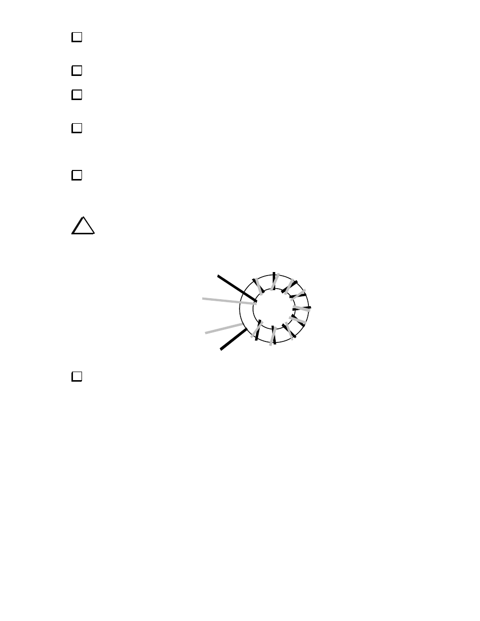
T1 is wound on a ferrite toroidal core (gray, FT37-43). Cut two 10" (25 cm) lengths of #26 enamel
wire, one red and one green. Twist the two wires together, crossing over each other about 3 to 4 times per
inch (1-2 times per cm). Then wind the twisted wires onto the core as shown below, using 10 turns. Each
pass through the core counts as one turn, and turns spacing should closely resemble the illustration.
i
The wires labeled (1) and (3) should originate from below the core, and wires (2) and (4)
from above it, as shown below. This will ensure that the transformer has the correct phasing.
3 (RED)
1 (GRN)
2 (GRN)
4 (RED)
Trim the leads of T1 to about 1/2" (12 mm) long. Completely remove the insulation from T1's leads
up to the edge of the core, using a solder pot or hot soldering iron tip. Do not attempt to burn off the
insulation using a match or lighter, as the flame may fuse the pairs of wire together, causing them to
become shorted. Another way to remove the insulation is to use fine sand paper.