Threshold – Elecraft KNB1 Manual User Manual
Page 8
Elecraft • www.elecraft.com • 831-662-8345
Circuit Details
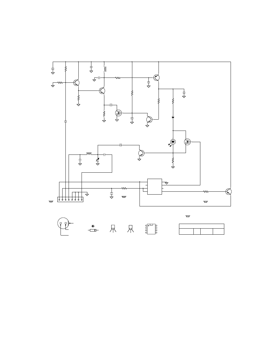
Q1 buffers the output of the K1’s receive mixer. Q2 amplifies the I.F. signal, then Q3 amplifies negative-going pulses.
The resulting positive-going pulses from Q3 drive the AGC amplifier, Q4/Q5, which holds Q2’s gain constant over a
wide range of I.F. levels. Pulses that exceed the forward bias voltage of D1, or D1+D2 (in the
H I
threshold case) drive
Q7 into saturation, effectively shorting out the I.F. path at the output of the band-pass filter (C1, L1, C2). The band-
pass filter delays the I.F. signal to allow the blanking signal to arrive at Q7 at about the same time as the noise pulse.
MCU U1 is controlled via the 6R/Aux data line. It turns the KNB1’s power on/off and selects
H I
or
L O
threshold.
= On bottom of PC board.
W. Burdick
N
N
N
Nooooiiiisssseeee G
G
G
Gaaaatttteeee
E. Swartz
6V = OFF
0V = ON
2N3906,
1 of 1
RRR
RFFFF A
A
A
Am
m
m
mpppp
12C509A
27K
GP5
GP4
VDD
GP3
GP2
GP1
GP0
VSS
RP2
.01
180
U1
R 1
P1
C5
5
6
7
8
1
2
3
4
6
5
1 2
3
4
5
6
7
8
E
B
C
1
2
3
4
5
6
7
8
CC
C
Coooonnnnttttrrrroooolllllllleeeerrrr
RP2
2
1
27K
C6
.01
Q2
To RF-J1
6
6
6
6V
V
V
V SSSSw
w
w
wiiiittttcccchhhh
3.9K
R 2
2N4124
6A
12C509A
K
K
K
KN
N
N
NBBB
B11
1
1 N
N
N
Nooooiiiisssseeee BBB
Bllllaaaannnnkkkkeeeerrrr
6R/AUX
RP1
3
4
470
L2
RP1
6
5
470
Q5
L1
C1
C3
RF IN
RF OUT
180
C2
50
10
C4
.01
2N7000
22 µH
75 µH
C9
.001
BB
B
Baaaannnndddd----PPPPaaaassssssss FFFFiiiilllltttteeeerrrr
2N4124
2N7000
S
G
D
RF SAMPLE
1N4148
C8
N
N
N
Nooooiiiisssseeee A
A
A
Am
m
m
mpppp
Q4
RP1
7
8
470
C10
2.2 µF
RP2
7
8
27K
Q1
2N4124
RP1
1
2
470
C11
0.1
BB
B
Buuuuffffffffeeeerrrr
A
A
A
AG
G
G
GCC
C
C
TT
T
Thhhhrrrreeeesssshhhhoooolllldddd
CC
C
Coooonnnnttttrrrroooollll
6NB
RP2
4
3
27K
Q7
RP1
9
10
470
D1
D2
Q6
BOTTOM VIEW
CATHODE
NOTCH
ANODE
2N4124
2N4124
2N7000
1N4148
(Green)
0V = HIGH THRESHOLD
6V = LOW THRESHOLD
C
Q8
2N3906
Q3
C7
.01
2N3906
LED (D2)
D
S
G
A
C
D
S
G
Elecraft
Rev. Sht.
Date
B y
C12
10
*
*
C13
.001
*
*
* C12 and C13 are on the rev. D (or later) PC board.
They must be soldered on the bottom on earlier boards.
** C8 is on the rev. C PC board only, and is not used.
+
12-20-00
or 1N4148