Elecraft KNB1 Manual User Manual
Page 5
5
i
In the following step, you’ll install a 1N4148 diode at D2, even thought the PC board has
an outline for an LED at this location. The LED (D2A) may be substituted later (see page 7).
Install a 1N4148 diode vertically at D2. The anode lead (non-banded end) should be inserted
into the hole nearest Q6 (round pad). The cathode lead (banded end) should be folded down and
inserted into the hole nearest Q7 (square pad). Bend the leads to hold D2 in place, then solder.
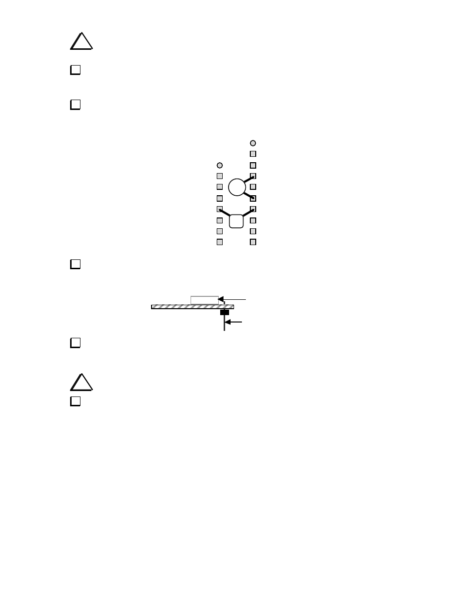
If your PC board is revision C, solder C12 (10 pF) and C13 (.001 µF, “102”) on the bottom
of the board as shown below, between the two resistor networks. Use short leads. Trim the leads
of the components in this area so the capacitors can be installed close to the bottom of the board.
C12
4
6
1
C13
7
1
5
Install 8-pin male connector P1 on the bottom of the PC board in the position indicated by its
component outline. Do not solder yet. Refer to the drawing below.
P1 (on bottom)
Components on top
Solder only pin 4 or 5 of P1. Verify that P1 is now perpendicular to the PC board and is
seated completely flat. If not, re-heat the soldered pin and press down on all of P1's pins until the
connector drops into place. Once the connector is seated correctly, solder the remaining pins.
i
U1 is static-sensitive. Before handling it, touch an unpainted, grounded surface.
Install 8-pin IC U1. Be sure to align the notched or dotted end of the IC with the notched end
of its PC board outline. Note: A socket is not supplied and is not needed for U1.