Elecraft KNB1 Manual User Manual
Page 6
6
Installation
Turn the K1 off and disconnect the power source.
Remove the top and bottom covers.
Remove C22 on the K1 RF board (at the right edge, near J1, the noise blanker connector).
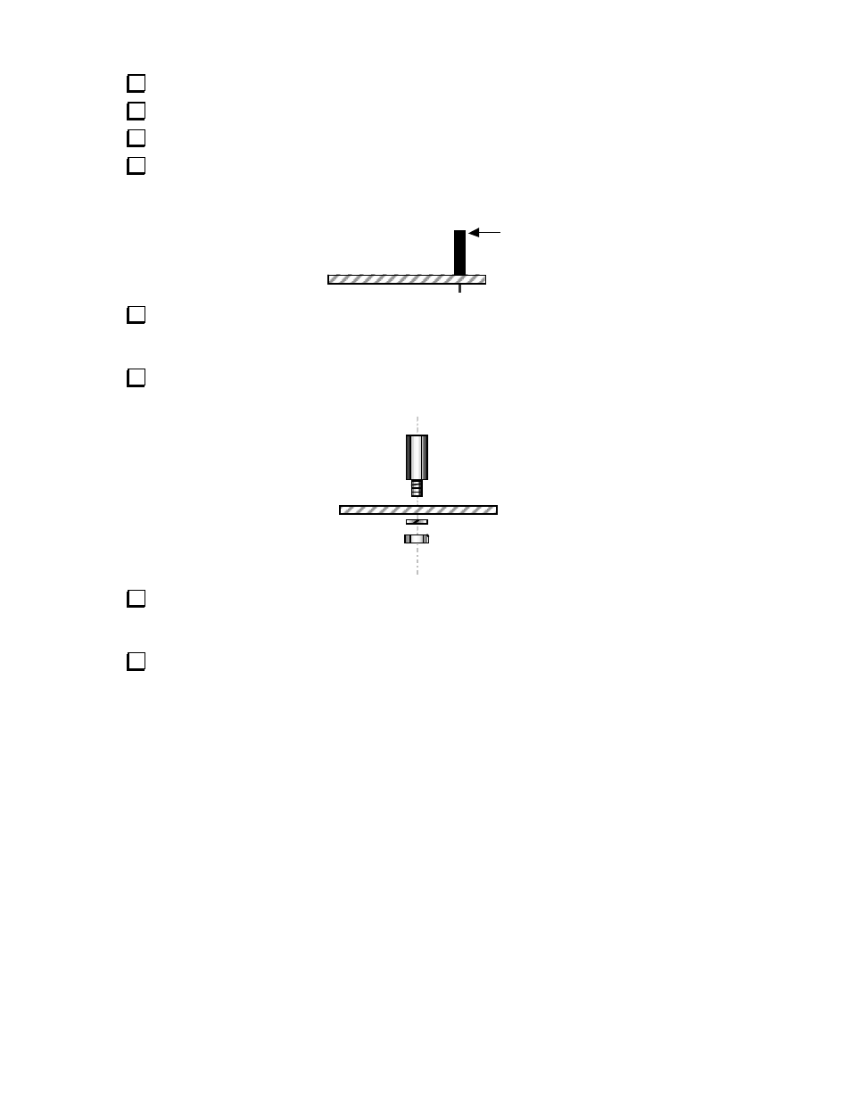
Install the 8-pin female connector on the RF board at J1 as shown by its outline. Do not
solder yet. The side view of J1, below, shows how it should appear once properly seated.
J1
Solder just pin 4 or 5 of J1, on the bottom of the RF board. Then, if the connector is not
sitting completely flat against the RF board (or is not vertical), reheat this pin and carefully press
the connector down. You may hear it snap into place. Then solder the remaining pins of J1.
Install the 7/16" male-female standoff on the top of the RF board as shown below, using a #4
internal-tooth lock washer and 4-40 nut.
Plug the noise blanker module into J1 on the RF board, being careful to line up all pins of the
connectors. Secure the module to the standoff using a 3/16" (4.7 mm) screw and one internal-
tooth lock washer.
Re-install the bottom cover.