Elecraft KNB1 Manual User Manual
Page 4
4
i
The toroid core for inductor L2 is marked with an orange dot to differentiate it
from L1. Be sure to use the correct cores in the following steps.
Inductor L1 is wound on the FT37-61 core (gray, with NO orange dot) using 16 inches (40
cm) of #26 enamel wire. To wind the inductor, “sew” the long end of the wire through the core
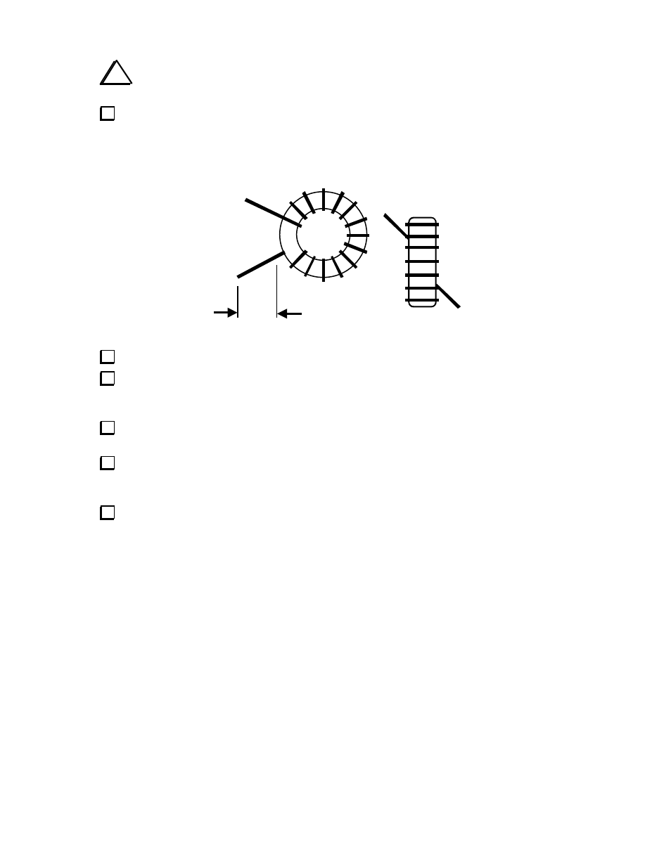
exactly 22 times. Each pass through the core counts as one turn. The winding should look like
the illustration below, except it will have 22 turns (the drawing shows only 14 turns).
Remove insulation
Spread out the turns of L1 so they occupy about 80-90% of the core’s circumference.
Cut L1's leads to about 1/2" (12 mm) long. Completely remove the enamel insulation from
the leads to within 1/8” (3 mm) of the core. The enamel wire provided can be easily heat-stripped
using a small amount of solder on the tip of your iron. Stripping using this method takes 4-6 sec.
Install L1 vertically on the PC board as shown by its component outline, then pull the leads
taut on the bottom of the board.
Trim and solder the leads of L1. When soldering, make sure that the solder binds well to the
leads. If the lead appears to be an “island” in a small pool of solder, chances are it is not making
good contact. Measure from pad to pad using an ohmmeter to verify the connection.
Inductor L2 is wound on the FT37-43 core (gray, with orange dot) using 15 inches (38 cm)
of #26 enamel wire. To wind the inductor, sew the long end of the wire through the core exactly
20 times. The winding should look like the illustration above, except with 20 turns.