EFCO S5600 Structural Glazed User Manual
Page 12
EFCO CORPORATION 7/2012 PART NO. Y306
Page 12 of 28
Series 5600 Silicone Structural Glazed Installation Instructions
2
1/4"
2 5/8"
ADA
P
TO
R
1/2"
MULL LENGTH
MULL LENGTH
IF R
E
Q
'D
A
A
(S
PLIC
E
LE
NGTH
MA
Y V
AR
Y)
AIR SEAL
@ MULLION.
4
1/
2"
5/
8"
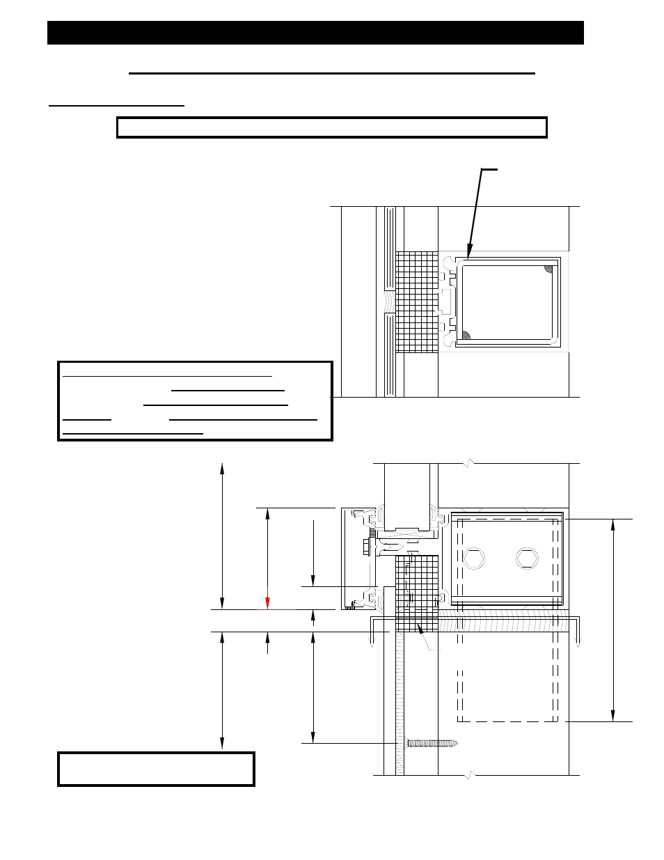
Section V: Vertical Jamb Splice Joints
Vertical Splice Joints
E.)
Where head clearance is
insufficient to allow top mullions
to be lifted over sleeve. A
retractable sleeve will be used.
The sleeve is taped in the top
mullion and dropped to stop
screw in mullion below.
F.)
Do not match drill anchors until a
check of expansion joints and
wall installation is made.
Note: Butt glazed mullion splice joints should occur at spandrel areas.
Mullion splice
sleeve with
bond breaker
tape
“A-A” Section Thru Splice
Note: All anchors must be fixed
before glazing begins.
Note: SSG Vertical Splice Locations EFCO
recommends that Vertical Splice Line should
be below the Intermediate Horizontal
Member, this will Minimize Shear Stress at
the Structural Seal Line.
- Windows Hung General Maintenance Instructions (19 pages)
- Windows Hung Understanding Condensation (6 pages)
- Windows Hung Installation (58 pages)
- E-Lite (19 pages)
- E-Shade (41 pages)
- 2 1/2" Center Tongue Sun Shade Clip (19 pages)
- S5500 Advanced (46 pages)
- S5500 Inside Glazed (48 pages)
- S5500 Outside Glazed (48 pages)
- S5500 Router & Jig (6 pages)
- S5500 SSG Captured (81 pages)
- S5500 SSG (53 pages)
- S5600 Concealed Vent (13 pages)
- S5600 Inside Glazed (29 pages)
- S5600 Outside Glazed (26 pages)
- S5600 Slope Glazed (23 pages)
- S5900 Inside Glazed (18 pages)
- S5900 Outside Glazed (16 pages)
- S5900 Structural Glazed (23 pages)
- 5500X Outside Glazed (60 pages)
- Duracast Pressure Plate (12 pages)
- 5800 Series (20 pages)
- 8700 Series Assembly Instructions Vol.1 (35 pages)
- 8700 Series Assembly Instructions Vol.2 (34 pages)
- 8700 Series Assembly Instructions Vol.3 (28 pages)
- 8700 Series Assembly Instructions Vol.4 (44 pages)
- 8700 Series Assembly Instructions Vol.5 (89 pages)
- 8700 Series Assembly Instructions Vol.6 (16 pages)
- 8700 Installation Instructions (68 pages)
- 8750XD (43 pages)
- 875X Wall Vent (31 pages)
- 401 Series Roto Vent for Storefront (14 pages)
- 401 Series Storefront (94 pages)
- 406 (T) Series (41 pages)
- 433 Series (90 pages)
- 525 Series (45 pages)
- 526 Series (50 pages)
- 960 Series (65 pages)
- WV410 (21 pages)
- 403X Series (29 pages)
- 406X Series (25 pages)
- 945 Series (50 pages)
- 955 Series (45 pages)
- 901 Series (52 pages)